
Welcome to the Verification and Validation guide!
This guide demonstrates how to use Innoslate for verification and validation. If you haven’t already, we recommend reading our Requirements Management and Analysis guide before proceeding.
According to the IEEE Standard for Systems and Software, Verification and Validation (V&V) “are used to determine whether the development products of a given activity conform to the requirements of that activity and whether the product satisfies its intended use and user needs.” The goal of V&V is to ensure the resultant product, service, or system being developed meets or exceeds customer expectations. Without implementing proper V&V procedures while engineering a system, it is highly likely the product, service, or system won’t even actually be able to be built, let alone function properly.
Innoslate facilitates these system lifecycle procedures with integrated tools and a new, purpose-built user interface called ‘Test Center.” Our purpose for integrating these tools is to decrease the amount of time it takes to complete the V&V processes, and therefore, encourage those processes to occur more frequently throughout the systems engineering lifecycle.
Validation
Before trying to verify the product, service, or system meets the design requirements and system models, it is important to first validate whether or not those requirements and models are correct. Beginning the validation process early in the lifecycle enhances the probability of success by identifying errors early on in the development phase and preparing for the verification process later in the lifecycle.
-
Requirements Validation
Requirements validation is an iterative process that should be done throughout the systems engineering lifecycle. Regularly questioning and analyzing the quality of each requirement ensures that at the end of your requirements gathering and capture efforts, you will be left with well-written and verifiable requirements.
Innoslate provides integrated tools to help automate requirements validation such as the “Quality Check” feature of ‘Documents View.’ The “Quality Check” feature is used to assess a requirement’s clarity, completeness, consistency, design implications, traceability, and verifiability. If you haven’t already, read the “Analyze Requirements” section of our Requirements Management and Analysis guide for more information on the “Quality Check” feature of ‘Requirements View’ and instructions on how to run it.
During this process, it is important to double-check that each requirement is traceable back to the origin of the requirement and every change has been tracked throughout the life of the requirement. Innoslate takes care of most of this automatically, by creating relationships between entities and the originally uploaded artifact and tracking changes to maintain a version history on every entity.
-
Model Validation
Model validation is another iterative process that should also be done throughout the systems engineering lifecycle. Regularly questioning and analyzing the quality of each model ensures, at the end of your behavioral and physical modeling efforts, you will be left with a model complete enough to be executable.
Innoslate provides integrated tools to help automate model validation as well, such as the ‘Intelligence’ tool to assess a model’s traceability, construction, naming conventions, and more. If you haven’t already, please read the “Ensuring Overall Model Quality” section of our Model-Based Systems Engineering guide for more information on the ‘Intelligence’ tool and instructions on how to run it. Other built-in tools include the ‘Discrete Event Simulator’ and the ‘Monte Carlo Simulator’ to help determine whether or not a model is executable and help reduce the uncertainty of a product, service, or system’s cost, schedule, and performance.
Verification
Now that you are sure that the correct requirements and system models are captured in Innoslate, you can begin the process of verifying the system built meets the previously validated design requirements and system models. This process in Innoslate is primarily accomplished using ‘Test Center,’ a hierarchical document-like display of Test Case entities with collapsible sections, status roll-up, and inline entity editing.
-
Add Verification Method Labels
Next, you must identify which method or methods of verification are most appropriate to use to verify each design requirement. To capture this information in Innoslate, follow the instructions below:
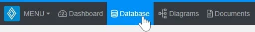
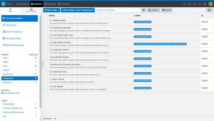
- Click the ‘Database’ button on the top navigation bar to navigate to ‘Database View.’
- To filter the view to only display Requirement entities, click ‘Requirement’ in the “By Class” section of the left sidebar.
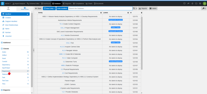
- Locate the ‘Labels’ in the Metadata Tab on the left sidebar. Determine and select which method of verification is appropriate to verify your requirement(s). Innoslate‘s default database schema provides five different verification method labels: Analysis, Demonstration, Inspection, Modeling & Simulation, and Test.
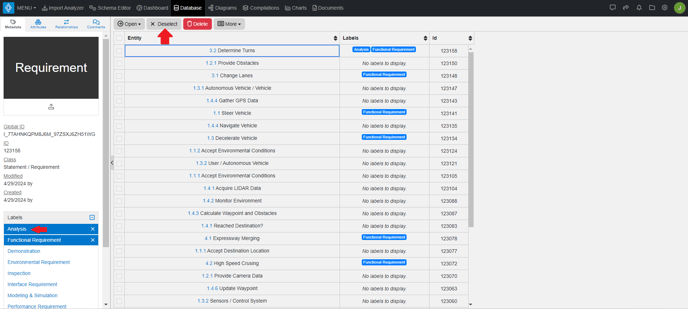
- Then press 'Deselect' on the toolbar and repeat 3 as needed, to add more than one Verification Method label to a requirement.
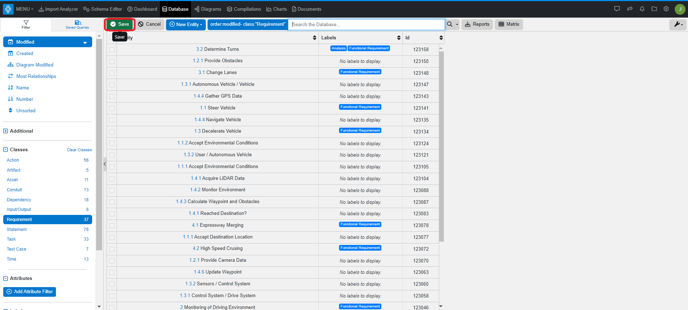
- Click the green checkmark button on the toolbar to save.
- Continue identifying appropriate verification methods and adding the corresponding labels until each requirement has a verification method specified.
- Click the ‘Database’ button on the top navigation bar to navigate to ‘Database View.’
-
Download a VCRM Report
Double-check to ensure each requirement has a verification method label by downloading a VCRM report. Follow the instructions below to download a VCRM report:
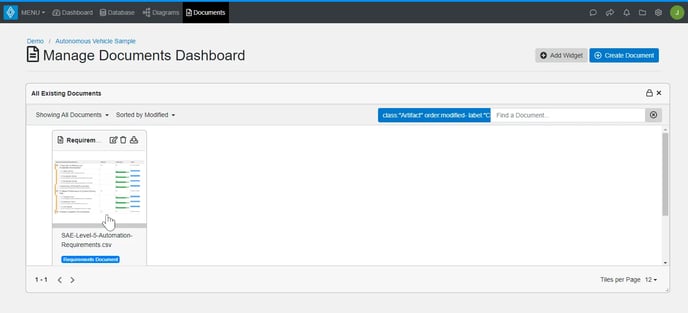
- Click ‘Documents’ in the top navigation bar to navigate to ‘Documents View.’ Select your document (in this case, “SAE Level-5 Automation Requirements”).

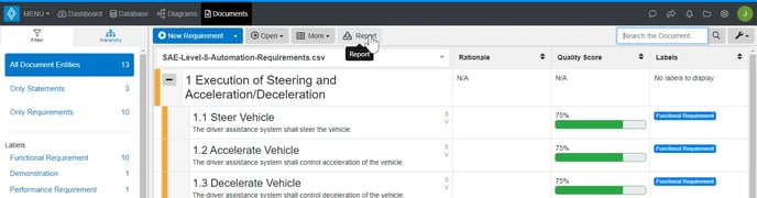
- Click the ‘Report’ button.
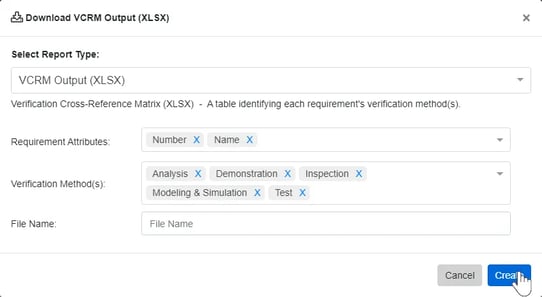
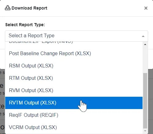
- Select ‘VCRM Output (XLSX)’ as your ‘Report Type.’
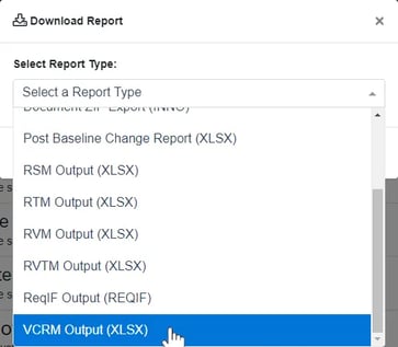
- Click ‘Create.’
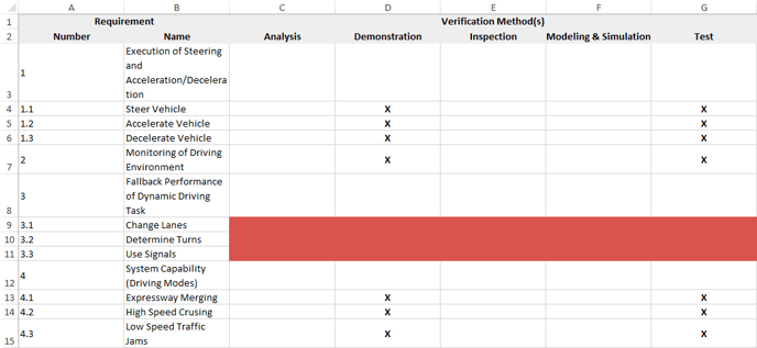
- Once the report has finished downloading, click on the downloaded file to open the VCRM in Excel. An example of the VCRM report is shown below:
-
Create a Test Suite
The first step in the verification process is to create a suite of tests to eventually run against the product, system, or service. Follow the instructions below to use ‘Test Center’ to create a test suite:
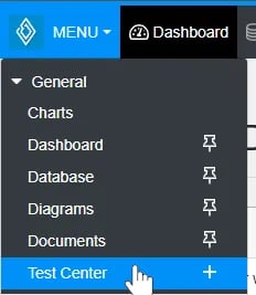
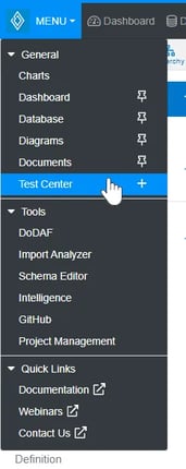
- Click to open the ‘MENU’ drop-down on the top navigation bar and select ‘Test Center’ under “General.”
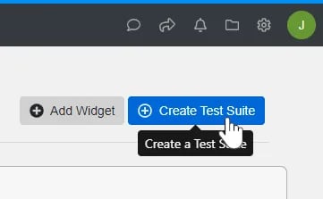
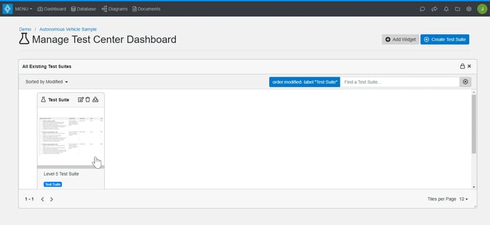
- Click ‘+ Create Test Suite’ in the upper right corner.
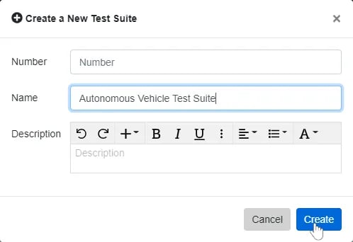
- The ‘Create a New Test Suite’ dialog will appear. Type in at least a name for the root Artifact entity of your new test suite, and then click the ‘Create’ button. In this case, we used the name “Autonomous Vehicle Test Suite.”
- ‘Test Center’ will refresh to display your newly created, empty test suite.
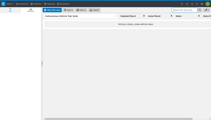
- Click the ‘New Test Case’ button.
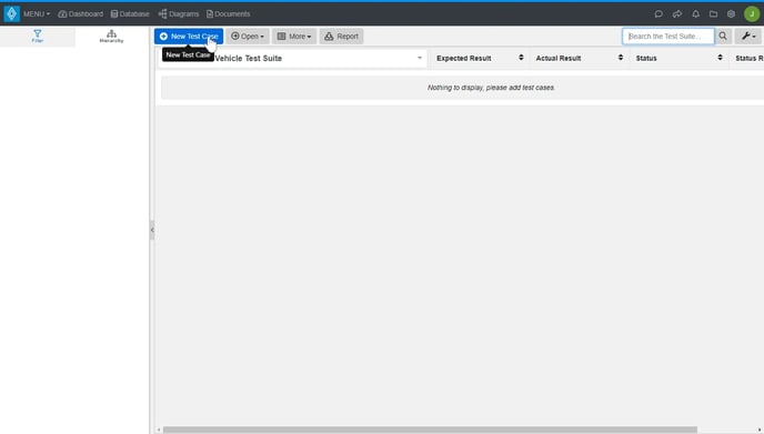
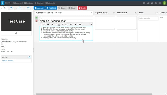
- This will navigate you to the end of the test suite where a new row has been added. Give your new Test Case entity a meaningful name and be sure to include the procedures necessary to perform the test in the entity’s description or decomposition. In this case, we used the name “Vehicle Steering Test.”
- Fill in the ‘Expected Result’ attribute with what conditions are necessary for the test to pass.
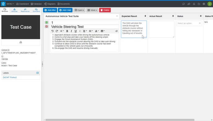
- Click the green checkmark button to save.
- Continue adding test cases until you are confident you have identified a procedure to verify each design requirement.
- Click to open the ‘MENU’ drop-down on the top navigation bar and select ‘Test Center’ under “General.”
-
Trace Test Cases to Requirements
It is important to maintain traceability throughout the verification process so that any engineer reviewing your work months, or even years, down the road can clearly understand what was tested and why. Follow the instructions below to trace your test cases to your design requirements:
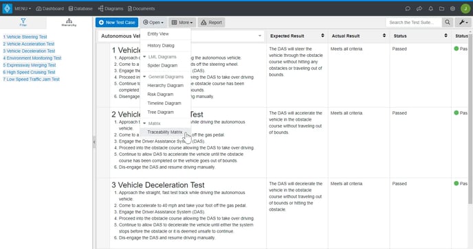
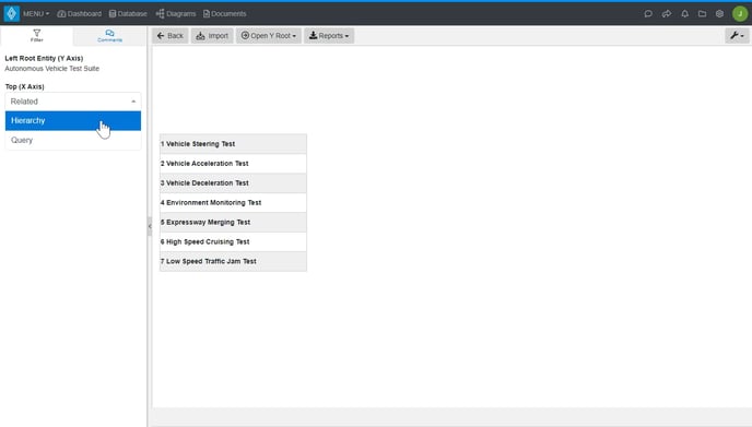
- Within ‘Test Center,’ click to open the ‘Open’ drop-down and select the ‘Traceability Matrix’ menu item under the “Matrix” section.
- Ensure the ‘Top (X Axis)’ is labeled ‘Hierarchy’ in the left sidebar.
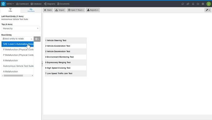
- Under ‘Root Entity,’ select the name of your requirements document’s root Artifact entity: “SAE-Label-5-Automation-Requirements.csv.”
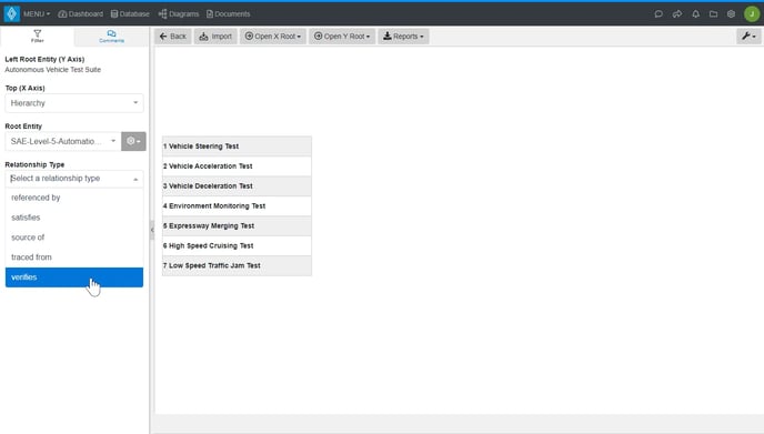
- Under ‘Relationship Type,’ select the name of the relation to compare. In this case, select “verifies.”
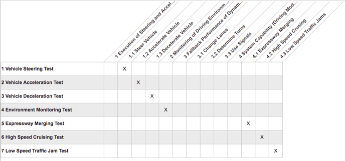
- Trace which individual Test Case entity from your test suite verifies which Requirement entity from your requirements document by clicking the cell in the matrix where the two intersect. An ‘X’ will appear in the cell indicating a verifies/verified by relationship has been added linking the two entities. You should end up with a matrix similar to the one pictured below:
- Click the ‘Save’ button to persist your changes to your project’s database.
- Within ‘Test Center,’ click to open the ‘Open’ drop-down and select the ‘Traceability Matrix’ menu item under the “Matrix” section.
-
Download an RVTM Report
- Click the ‘Documents’ button on the top navigation bar to navigate to ‘Documents View.’

- Select your Requirements Document: “SAE Level-5 Automation Requirements.”
- From within your Requirements Document, click the ‘Report’ button in the toolbar.
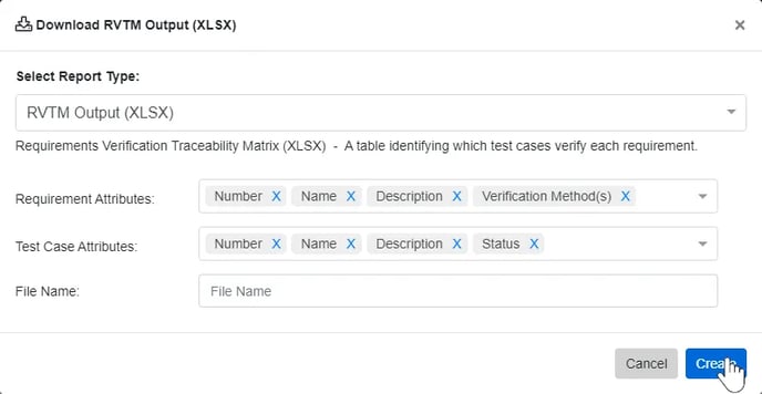
- For ‘Report Type,’ select ‘RVTM Output (XLSX).’
- Click the ‘Create’ button to generate and automatically download an RVTM report.
- Once the report has finished downloading, click on the downloaded file to open the RVTM in Excel.
- Click the ‘Documents’ button on the top navigation bar to navigate to ‘Documents View.’
-
Run a Test Cycle
Now that you have proven traceability and test coverage, it is time to actually perform all the procedures to run all the tests against your product, service, or system. Follow the instructions below to run your first test cycle:
- Click to open the ‘MENU’ drop-down on the top navigation bar and select the ‘Test Center’ menu item under the “General.”
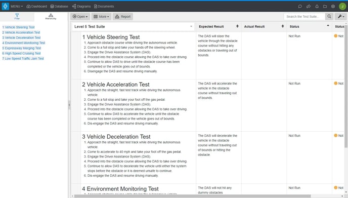
- From the ‘Test Center,’ select your test suite (in this case, we are using “Level 5 Test Suite” from the example project).
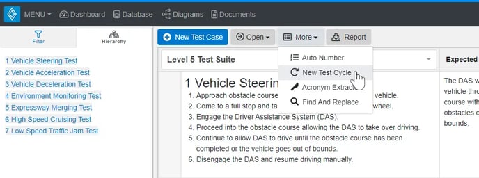
- Click on the ‘New Test Cycle’ button under the ‘More’ drop-down.
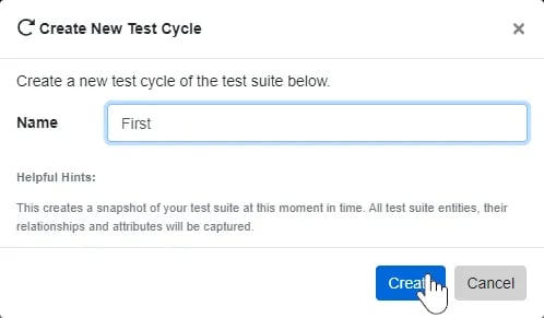
- A ‘Create New Test Cycle’ dialog will appear. For ‘Name,’ type in “First.” Click the blue ‘Create’ button.
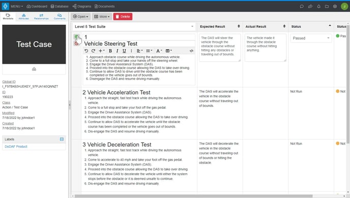
This sets the ‘Actual Result’ and ‘Status’ attributes of every test case in your suite back to blank and “Not Run,” respectively. ‘Test Center’ will refresh to display the changes, as shown below.
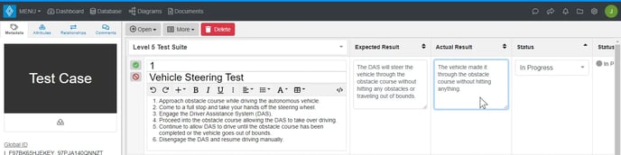
- Click anywhere within the first test case’s displayed row to enter its edit mode.
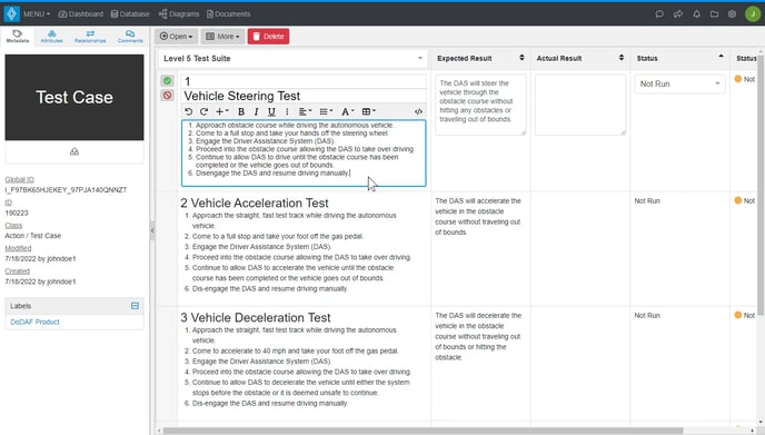
- Change the ‘Status’ attribute of that test case to “In Progress.”
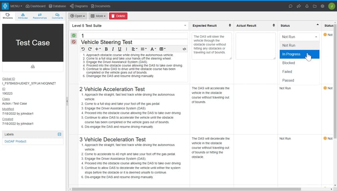
- Click the green checkmark button to save.
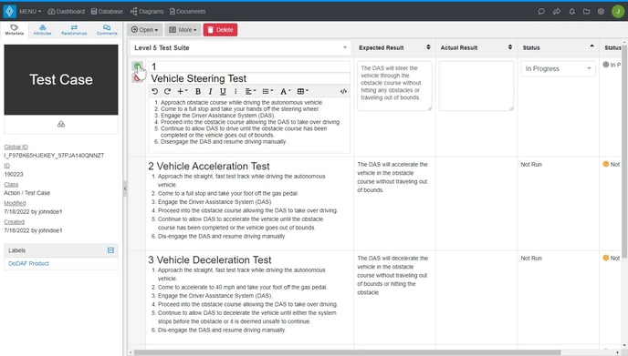
- Using the verification method specified by the test case, perform the test procedure on the product, service, or system.
- Fill in the ‘Actual Result’ attribute with your observations of what actually happened as a result of the test procedure.
- Determine if the test has passed, failed, or otherwise, and then change the ‘Status’ attribute to reflect your decision.
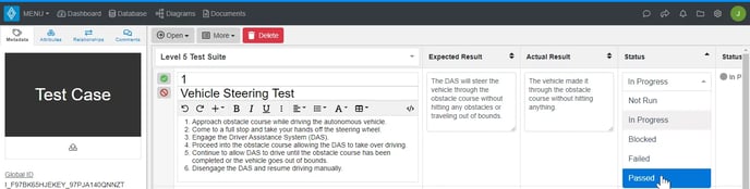
- Click the green checkmark button to save.
- Continue testing until every test in the suite has been performed.
- Click to open the ‘MENU’ drop-down on the top navigation bar and select the ‘Test Center’ menu item under the “General.”
-
Download a Test Cases Report
You have executed each test procedure and determined whether each test passed, failed, or otherwise using that test’s specified verification method. You can now download a Test Cases report as proof of verification of your product, service, or system. Follow the instructions below to download a Test Cases report:
- From your ‘Test Suite,’ click the ‘Report’ button.
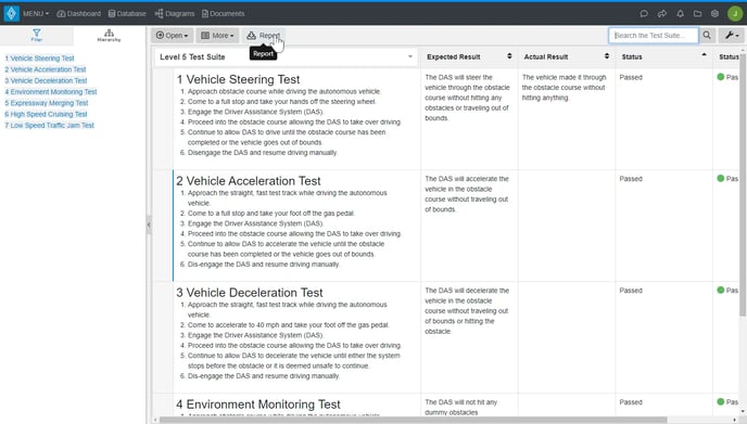
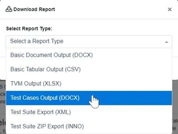
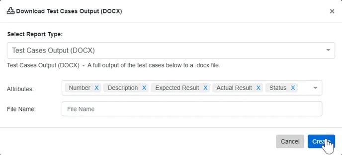
- Select ‘Test Cases Output (DOCX)’ as your ‘Report Type.’
- Click ‘Create.’
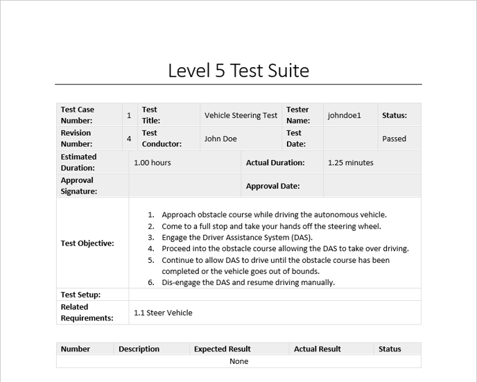
- Once the report has finished downloading, click on the downloaded file to open the Test Cases in Word. An example of the Test Cases report is shown below:
- From your ‘Test Suite,’ click the ‘Report’ button.
-
- Click ‘Documents’ in the top navigation bar to navigate to ‘Documents View.’ Select your document (in this case, “SAE Level-5 Automation Requirements”).