
Using Asset Diagrams
| Function | Description |
|---|---|
| Creating Asset Diagrams | Using ‘Diagrams View’ in Innoslate, you can create a new ‘Asset Diagram.’ |
| Asset Diagram Constructs | The ‘Asset Diagram’ supports two unique diagram constructs: an ‘Asset’ and a ‘Conduit.’ |
| Adding an Asset | An ‘Asset’ construct can be added to an ‘Asset Diagram’ via drag-and-drop. |
| Modify an Asset | An overview of the editing options for an Asset Construct. |
| Adding a Conduit | A ‘Conduit’ construct can be added to an ‘Asset Diagram’ via drag-and-drop. |
| Modify a Conduit | An overview of the editing options for a Conduit Construct. |
| Removing a Construct | A construct can be easily removed from an ‘Asset Diagram.’ |
| Adding Pictures to an Asset Diagram | Add a background picture or to a specific construct in an Asset Diagram. |
| Editing Multiple Assets | An overview of the editing options for multiple Assets when selected. |
| Asset Diagram Settings | Review of the Settings options for the Asset Diagram. |
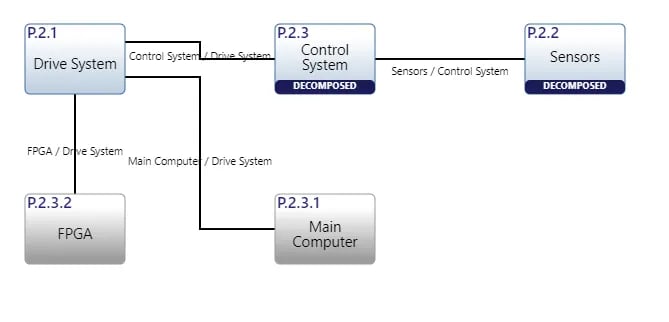
The ‘Asset Diagram’ is traditionally known as a block diagram or a physical block diagram. This diagram conforms to the LML Specification 1.4 definition of an ‘Asset Diagram’, which requires a diagram representation of the physical components of a system model.
Creating Asset Diagrams
Within the ‘Diagrams Dashboard,’ users can create a new diagram by clicking the ‘Create Diagram’ button in the top right corner of the page.

Clicking the ‘Create Diagram’ button will open the Create Diagram dialog where you will be directed through the process of creating a new diagram.
- Choose Which Type of Diagram to Create
In step 1, select ‘Asset Diagram,’ under ‘LML,’ as your diagram type.
Click the ‘Next’ button.

- Specify New Root Action Information
In step 2, you will be prompted to input a diagram ‘Name’ (required), ‘Number’ (optional), and ‘Description’ (optional). Then, click the ‘Finish’ button to save and automatically open your new Asset Diagram.
Asset Diagram Constructs
The ‘Asset Diagram’ supports two unique diagram constructs, an ‘Asset’ and a ‘Conduit.’ Each diagram construct is described in more detail below:
-
Asset
This construct is used to capture the physical components of a system.
In the system model, a simple Asset entity is generated to represent an ‘Asset’ construct with no additional diagram-specific information. Innoslate’s default database schema includes labels to specify the type of this Asset entity as a(n) Architecture, Block, Context, Environment, External System, Facility, Infrastructure, Materiale, Organization, Package, Personnel, Segment, Service, Subsystem, and/or System.
In the diagram, this construct is represented as a rounded block containing the number and name of the ‘Asset.’

-
Conduit
This construct is used to capture the relationships between the physical components of a system.
In the system model, a Conduit entity is generated to represent a ‘Conduit’ construct with a connects to relationship to each of the entities which represent the two connected constructs. Innoslate’s default database schema includes labels to specify the type of this Conduit entity as a(n) Aggregation, Association, Cable, Composition, Downlink, Interface, Network, Pipe, Roadway, Uplink, and/or Wireless.
In the diagram, this construct is represented as a solid line connecting two ‘Asset’ constructs and a line label containing the name of the ‘Conduit.’
Adding an Asset
An ‘Asset’ construct can be added to an Asset Diagram via drag-and-drop.
- Within an Asset Diagram, click the ‘Asset’ icon in the ‘New’ tab of the left sidebar and continue to hold down the left mouse button.

- Drag the ‘Asset’ icon over to the adjacent diagram canvas.


Notice the ‘Asset’ stays selected once it has been dropped. Since it is selected, the toolbar changes to include buttons for functions that can be used on the construct. The left sidebar also changes to include additional ‘Metadata,’ ‘Attributes’ and ‘Relationships’ tabs for modification.
The default Innoslate Schema does not have attributes for Assets as this can depend on the project and its purpose. To modify the attributes, users will need to go to the Schema Editor and add attributes.
4. Once added to the diagram, enter a meaningful ‘Name’ for your new ‘Asset’ via the ‘Attributes’ tab of the left sidebar (focused automatically for convenience).

* Note: The above process describes using the ‘New’ tab of the left sidebar, which automatically generates a new entity to represent each new diagram construct. If you would like to reuse existing entities from your database to represent a new construct, use the ‘Existing’ tab instead.
Modifying an Asset
When an Asset is selected, the top toolbar options provide options as shown and explained below.

The Open dropdown will open up the Asset into other views. For more clarification on the Open dropdown please see here.

This button will 'Bold' the name for the Asset in the construct on the canvas.

Using the HTML Color Picker that drops down from the 'Change Text Fill Color Option', users can change the text color of the Asset's name in the construct on the canvas by selecting the color associated close to the desired color and selecting from the color canvas in the dropdown or simply inputting in the fields the proper codes and numbers.

To change the color of the construct of the Asset construct on the Canvas, the 'Change Fill Color' option can be used with the HTML Color Picker dropdown, by selecting the color associated close to the desired color and selecting fromt he color canvas in the dropdown or simply inputting in the fields the proper codes and numbers.

The 'Reset color back to default' option will reset the construct fill and text color back to gray and black.

The 'Mark External' option allows users to exclude an Asset from the diagram's root entity's decomposition. It adds an 'External' label and changes the Asset's color to a darker gray to distinguish it (as shown below). The Mark External button then also changes to 'Mark Internal.' If users want to include the Asset back into the decomposition and remove the label, they can use the 'Mark Internal' button. This feature is particularly useful when including an Asset in a diagram that does not need to be part of the hierarchy.
Adding a Conduit

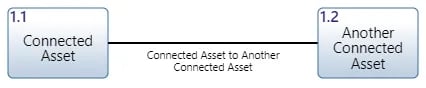
A ‘Conduit’ construct can be added to an ‘Asset Diagram‘ via drag-and-drop. The example used on this page connects two ‘Asset’ constructs with a ‘Conduit’ construct.
- Within an Asset Diagram, select the ‘Asset’ you would like connected to another ‘Asset.’

- Click one of the green circles on the selected ‘Asset’ and continue to hold down the left mouse button.

- Drag the green circle over to another ‘Asset’ of your choice.

- When the other ‘Asset’ box highlights green, release the left mouse button to drop the new ‘Conduit’ and add it to the diagram.

Notice the ‘Conduit’ stays selected once it has been dropped. Since it is selected, the toolbar changes to include buttons for functions that can be used on the construct. The left sidebar also changes to include additional ‘Metadata,’ ‘Attributes’ and ‘Relationships’ tabs.
- Once added to the diagram, enter a meaningful ‘Name’ for your new ‘Conduit’ via the ‘Attributes’ tab of the left sidebar (focused automatically for convenience).

- Click the ‘Save’ button located on the toolbar to persist your changes to your project’s database.

Note that users also may drag the name of the of Conduit on the canvas, by selecting the name and dragging it. Upon doing so, a line will appear to indicate the Conduit label's name, as indicated in the blue circle below.

Modifying a Conduit

When the conduit is selected, users will notice the top toolbar provides options to modify its appearance. Below we will go over each option.

The Open dropdown will open up the conduit into other views. For more clarification on the Open dropdown please see here.

This button will 'Bold' the label for the Conduit on the canvas.

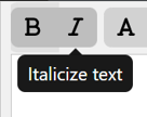
This button will 'Italicize' the label for the Conduit on the canvas.
.webp?width=254&height=292&name=Diagrams%20Change%20Text%20Fill%20Color%203%20(1).webp)
Using the HTML Color Picker that drops down from the 'Change Text Fill Color Option', users can change the text color of the label to the conduit the canvas by selecting the color associated close to the desired color and selecting from the color canvas in the dropdown or simply inputting in the fields the proper codes and numbers.
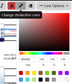
To change the color of the Conduit on the Canvas, the 'Change Stroke/line color option' can be used with the HTML Color Picker dropdown, by selecting the color associated close to the desired color and selecting fromt he color canvas in the dropdown or simply inputting in the fields the proper codes and numbers.

The 'Reset color back to default' option will bring the color of the Conduit's line and text colors back to black.
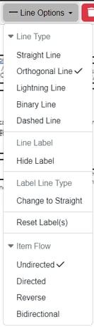
The line construct on the canvas for the Conduit can be changed with the options under the 'Line Options' dropdown. Users may change the line to be Straight, Orthogonal, a Lightning Bolt, Binary or Dashed. This dropdown also provides features to Hide or Show the conduit's label, or change the conduit's line to the label be straight or curved. The Reset Label option will reset the conduit back to straight and make the label of the conduit appear on the line of the construct. The Item Flow options will add arrows to the line for users that need to show flow. The flow options are Undirected, Directed, Reverse or Bidirectional.
Removing a Construct
A construct can be easily removed from an ‘Asset Diagram.’
- Within an ‘Asset Diagram,’ select the construct you wish to remove. This will make the toolbar appear with red Remove buttons as show below.

- Click the ‘Remove’ button to remove the construct from the diagram (as the default action).


-
The ‘Remove’ button also includes a drop-down menu where you can select ‘Delete from Database’ or the default option of ‘Remove from Diagram.’
Adding Pictures to the Asset Diagram

The Asset Diagram in Innoslate stands out for its unique feature that allows users to attach pictures to Asset constructs, displaying them directly on the diagram canvas. Users also have the option to add background pictures to enhance their Asset Diagrams. This section will delve into these features.
Adding a Picture to an Asset Construct

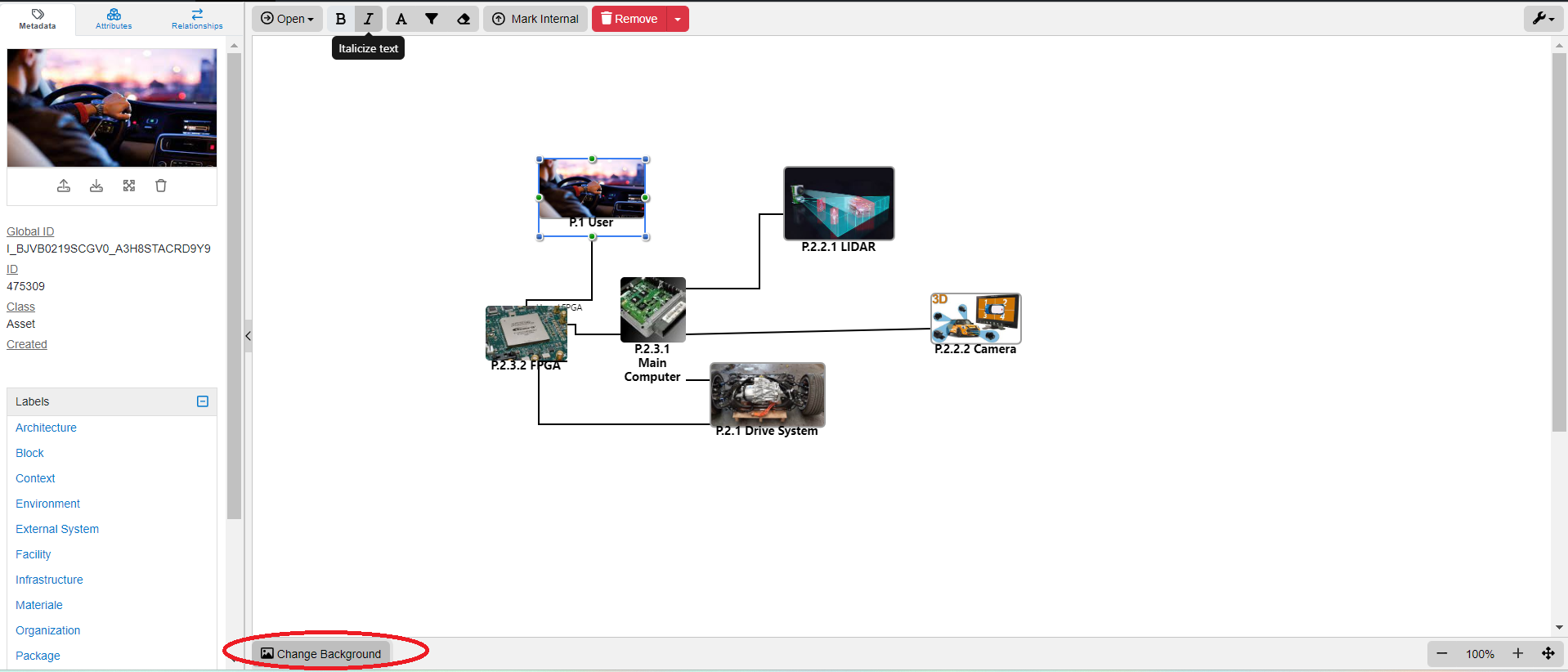
To add a picture to an Asset, this will be done on the left sidebar under the Metadata Tab. There is an upload icon right under the Asset indicator in this tab for users to upload their picture. Upon clicking on the Upload image button, the PC's File System will pop up to find the picture file to upload.

When the picture is uploaded, it will reflect in the box and appear in the Diagram.

The above four options underneath the picture will appear as shown above. The options from left to right are to Upload a new picutre, Download the picture, View the picture in full size and to Delete it.
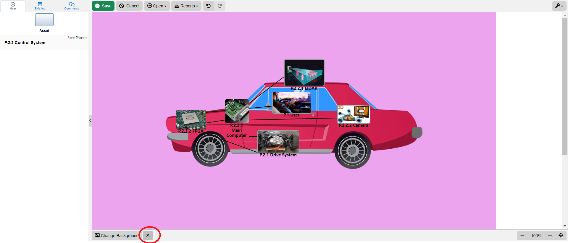
Add a Background Image to an Asset Diagram
Within the Asset Diagram toolbar at the bottom, you will find a 'Change Background' button. This feature allows you to upload a picture as the background for your diagram. Simply click on the button to access your PC's File System and select the desired image to set as the background.
Upon adding the picture, note the 'X' button appear next to the 'Change Background' button so that users may remove it.
⚠️File sizes can be no larger than 100MB on Innoslate Cloud. This size can be configured for Innoslate Enterprise instances.
⚠️File types can be any image files. Note, GIFs will not animate on the canvas, but will animate when expanding the full size of the picture and on the Metadata Tab.
Multiple Assets Selected on Canvas

Users may drag their cursor outside of the constructs and a box will appear to select as many multiple entites the user desires. Many features on the top toolbar will appear upon doing so for the user to utilize. Let's go over each option as highlighted below.


Users may Bold all the names of the multiple entities selected on the canvas.

Users may Italicize all the names of the multiple entities selected on the canvas.

Using the HTML Color Picker that drops down from the Text Fill Color Option, users can change the text color of the multiple entities selected on the canvas by selecting the color associated close to the desired color simply inputting in the fields the proper codes and numbers.

Using the HTML Color Picker that drops down from the Text Fill Color Option, users can change the color of the constructs of the multiple entities selected on the canvas.

Using the HTML Color Picker that drops down from the Change Stroke/Line Color Option, users can change the color that borders the constructs of the multiple entities selected on the canvas.

The Reset color back to default option will change the multiple entities selected on the canvas back to the default gray and black colors.

This selection will align the constructs vertically for the multiple entities selected on the canvas.

This selection will align the constructs horizontally for the multiple entities selected on the canvas.
Clone Shape

The Clone Shape option is to bring size uniformity to the diagram's constructs. When this option is selected, the green highlighed entity will be what the other constructs clone to so they are all the same size.
Asset Diagram Settings

The Settings dropdown is the Wrench Icon on the top right of the toolbar frame. The below options are shown for this dropdown for the Asset Diagram.
Users may generate a Systems Requirements Document (SRD) right from their Asset Diagram.
Users may also hide/show External Assets and/or Cross-Project Indicators.

Users may Auto Number their constructs, add a prefix and/or auto number on a single level. The below window will appear for users to choose from those options.

The final options provide users to reset their diagram, layout the diagram and go directly to the Help Center page on the Asset Diagram for convenience.

Hide Sidebar on the Left of the Toolbar Frame

Can't find the left sidebar or need to hide it for presentation purposes? Be sure to note the Hide Sidebar option on the left of the Toolbar Frame.
Tutorial Video
To continue learning about LML Diagrams, Click Here.
(Next Article: Spider Diagram)