
Using IDEF0 Diagrams
| Function | Description |
|---|---|
| Creating IDEF0 Diagrams | Using ‘Diagrams View’ in Innoslate, you can create a new ‘IDEF0 Diagram.’ |
| IDEF0 Diagram Constructs | The ‘IDEF0 Diagram’ supports five unique diagram constructs: a ‘Function,’ a ‘Mechanism,’ an ‘Input,’ an ‘Output,’ and a ‘Control.’ |
| Adding a Function | A ‘Function’ construct can be added to an ‘IDEF0 Diagram’ via drag-and-drop. |
| Adding a Mechanism | A ‘Mechanism’ construct can be added to an ‘IDEF0 Diagram’ via drag-and-drop. |
| Adding an Input | An ‘Input’ construct can be added to an ‘IDEF0 Diagram’ via drag-and-drop. |
| Adding an Output | An ‘Output’ construct can be added to an ‘IDEF0 Diagram’ via drag-and-drop. |
| Adding a Control | A ‘Control’ construct can be added to an ‘IDEF0 Diagram’ via drag-and-drop. |
| Adding a Resource | A 'Resource' can be added to an'IDEF0 Diagram' via the Action's Entity View. |
| Removing a Construct | A construct can be easily removed from an ‘IDEF0 Diagram.’ |
An IDEF0 Diagram is a functional modeling method designed to model the decisions, actions, and activities of an organization or system.

Creating IDEF0 Diagrams
Within the ‘Diagrams Dashboard,’ users can create a new diagram by clicking the ‘ New Diagram’ button in the top right corner of the page.
.webp?width=670&name=create_activity-2%20(1).webp)
Clicking the ‘ New Diagram’ button will open the New Diagram dialog where you will be directed through the process of creating a new diagram.
Create an IDEF0 Diagram
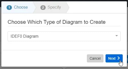
- Choose Which Type of Diagram to Create
In step 1, select ‘IDEF0 Diagram,’ under ‘General,’ as your diagram type.
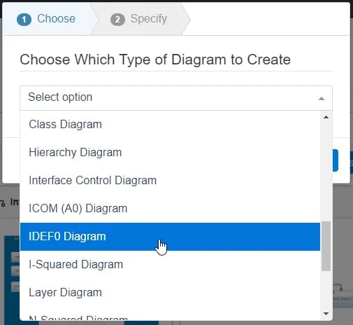
Click the ‘Next’ button.
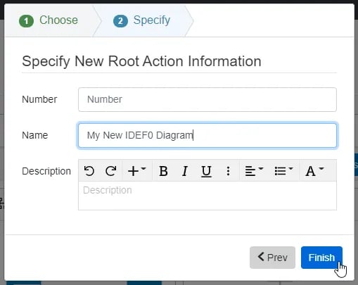
- Specify New Root Action Information
In step 2, you will be prompted to input a diagram ‘Name,’ ‘Number’ (optional), and ‘Description’ (optional). Then, click the ‘Finish’ button to save and automatically open your new IDEF0 Diagram.
IDEF0 Diagram Constructs
The ‘IDEF0 Diagram’ supports six unique diagram constructs:
- Function
- Mechanism
- Input
- Output
- Control
- Resource
-
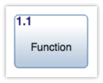
Function
This construct is used to represent the classic systems engineering function or task.
In the system model, a simple Action entity is used to represent a ‘Function’ construct with no additional diagram-specific information. By default, Innoslate’s database schema includes labels to specify the type of this Action entity as a(n) Activity, Capability, Function, Mission, Process, Program, Project, Task, and/or Use Case.
In the diagram, this construct is represented as a rounded block containing the number and name of the ‘Function.’
-
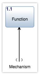
Mechanism
This construct is used to capture the physical means of performing a system function.
In the system model, an Asset entity is used to represent a ‘Mechanism’ construct with a performs relationship to the entity which represents the ‘Function’ construct being pointed to. By default, Innoslate’s database schema includes labels to specify the type of this Asset entity as a(n) Architecture, Context, Environment, External System, Facility, Infrastructure, Materiale, Organization, Package, Personnel, Segment, Service, Subsystem, and/or System.
In the diagram, this construct is represented as an arrow (directed line) that points up to the bottom of a ‘Function’ construct.
-
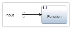
Input
This construct is used to capture anything introduced into the system being modeled.
In the system model, an Input/Output entity is used to represent an ‘Input’ construct with a received by relationship and a relationship attribute, 'Trigger set to 'No', to the entity which represents the ‘Function’ construct being pointed to. By default, Innoslate’s database schema includes labels to specify the type of this Input/Output entity as Analog, Digital, Event, Mixed, Physical, Product, Response, and/or Verbal.
In the diagram, this construct is represented as an arrow (directed line) that points toward a ‘Function’ construct from the left.
-
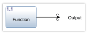
Output
This construct is used to capture anything produced by the system being modeled.
In the system model, an Input/Output entity is used to represent an ‘Output’ construct with a generated by relationship to the entity which represents the ‘Function’ construct being pointed away from. By default, Innoslate’s database schema includes labels to specify the type of this Input/Output entity as Analog, Digital, Event, Mixed, Physical, Product, Response, and/or Verbal.
In the diagram, this construct is represented as an arrow (directed line) that points away from the right of a ‘Function’ construct.
-
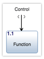
Control
This construct is used to capture system components that regulate the behavior of other system components.
In the system model, an Input/Output entity is used to represent a ‘Control’ construct with a received by relationship and a relationship attribute, 'Trigger set to 'Yes', to the entity which represents the ‘Function’ construct being pointed to. By default, Innoslate’s database schema includes labels to specify the type of this Input/Output entity as Analog, Digital, Event, Mixed, Physical, Product, Response, and/or Verbal.
In the diagram, this construct is represented as an arrow (directed line) that points down to the top of a ‘Function’ construct.
-
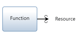
Resource
Within Innoslate's IDEF0 framework, this element visually depicts a physical object that is produced by a function.
In the system model, a Resource entity is used to represent a ‘Resource’ construct with either a consumed by/consumes, produced by/produces or a seized by/seizes relationship to an Action entity.
In the IDEF0 diagram, this construct is represented as an arrow pointing to the right of the Function the Resource is produced by.
Adding a Function
A ‘Function’ construct can be added to an ‘IDEF0 Diagram’ via drag-and-drop.
- Within an ‘IDEF0 Diagram,’ click the ‘Function (Action)’ icon in the ‘New’ tab of the left sidebar and continue to hold down the left mouse button.

- Drag the ‘Function’ icon over to the adjacent diagram canvas.

- Release the left mouse button while over the diagram canvas to drop the new ‘Function’ and add it to the diagram. The ‘Function’ will automatically snap to the nearest invisible grid intersection, which may be quite far from where it was dropped. The invisible grid intersections are fairly far apart in the ‘IDEF0 Diagram’ in order to leave adequate space for arrows between ‘Function’ constructs.

Notice the ‘Function’ stays selected once it has been dropped. Since it is selected, the toolbar changes to include buttons for functions that can be used on the construct. The sidebar also changes to include additional ‘Metadata,’ ‘Attributes,’ and ‘Relationships’ tabs.
- Once added to the diagram, enter a meaningful ‘Name’ for your new ‘Function’ via the ‘Attributes’ tab of the left sidebar (focused automatically for convenience).

- Click the ‘Save’ button located on the toolbar to persist your changes to your project’s database.

* Note: The above process describes using the ‘New’ tab of the left sidebar, which automatically generates a new entity to represent each new diagram construct. If you would like to reuse existing entities from your database to represent a new construct, use the ‘Existing’ tab instead.
Adding a Mechanism
A ‘Mechanism’ construct can be added to an ‘IDEF0 Diagram’ via drag-and-drop.
- Within an ‘IDEF0 Diagram,’ click the ‘Mechanism (Asset)’ icon in the ‘New’ tab of the left sidebar and continue to hold down the left mouse button.

- Drag the ‘Mechanism’ icon over to the destination ‘Function’ of your choice.

- When the ‘Function’ box highlights green, release the left mouse button to drop the new ‘Mechanism’ and add it to the diagram.

Notice the ‘Mechanism’ stays selected once it has been dropped. Since it is selected, the toolbar changes to include buttons for functions that can be used on the construct. The sidebar also changes to include additional ‘Metadata,’ ‘Attributes,’ and ‘Relationships’ tabs.
- Once added to the diagram, enter a meaningful ‘Name’ for your new ‘Mechanism’ via the ‘Attributes’ tab of the left sidebar (focused automatically for convenience).

- Click the ‘Save’ button located on the toolbar to persist your changes to your project’s database.

* Note: The above process describes using the ‘New’ tab of the left sidebar, which automatically generates a new entity to represent each new diagram construct. If you would like to reuse existing entities from your database to represent a new construct, use the ‘Existing’ tab instead.
Adding an Input
An ‘Input’ construct can be added to an ‘IDEF0 Diagram’ via drag-and-drop.
- Within an ‘IDEF0 Diagram,’ click the ‘Input/Output/Control’ icon in the ‘New’ tab of the left sidebar and continue to hold down the left mouse button.

- Drag the ‘Input/Output/Control’ icon over to the destination ‘Function’ of your choice.

- When the ‘Function’ box highlights green, release the left mouse button over the “Input” section to drop the new ‘Input’ and add it to the diagram.

Notice the ‘Input’ stays selected once it has been dropped. Since it is selected, the toolbar changes to include buttons for functions that can be used on the construct. The sidebar also changes to include additional ‘Metadata,’ ‘Attributes,’ and ‘Relationships’ tabs.
- Once added to the diagram, enter a meaningful ‘Name’ for your new ‘Input’ via the ‘Attributes’ tab of the left sidebar (focused automatically for convenience).

- Click the ‘Save’ button located on the toolbar to persist your changes to your project’s database.

* Note: The above process describes using the ‘New’ tab of the left sidebar, which automatically generates a new entity to represent each new diagram construct. If you would like to reuse existing entities from your database to represent a new construct, use the ‘Existing’ tab instead.
Adding an Output
An ‘Output’ construct can be added to an ‘IDEF0 Diagram’ via drag-and-drop.
-
Within an ‘IDEF0 Diagram,’ click the ‘Input/Output/Control’ icon in the ‘New’ tab of the left sidebar and continue to hold down the left mouse button.

-
Drag the ‘Input/Output/Control’ icon over to the destination ‘Function’ of your choice.

-
When the ‘Function’ box highlights green, release the left mouse button over the “Output” section to drop the new ‘Output’ and add it to the diagram.

Notice the ‘Output’ stays selected once it has been dropped. Since it is selected, the toolbar changes to include buttons for functions that can be used on the construct. The sidebar also changes to include additional ‘Metadata,’ ‘Attributes,’ and ‘Relationships’ tabs.
-
Once added to the diagram, enter a meaningful ‘Name’ for your new ‘Output’ via the ‘Attributes’ tab of the left sidebar (focused automatically for convenience).

-
Click the ‘Save’ button located on the toolbar to persist your changes to your project’s database.

* Note: The above process describes using the ‘New’ tab of the left sidebar, which automatically generates a new entity to represent each new diagram construct. If you would like to reuse existing entities from your database to represent a new construct, use the ‘Existing’ tab instead.
Adding a Control
A ‘Control’ construct can be added to an ‘IDEF0 Diagram’ via drag-and-drop.
- Within an ‘IDEF0 Diagram,’ click the ‘Input/Output/Control’ icon in the ‘New’ tab of the left sidebar and continue to hold down the left mouse button.

- Drag the ‘Input/Output/Control’ icon over to the destination ‘Function’ of your choice.

- When the ‘Function’ box highlights green, release the left mouse button to drop the new ‘Control’ and add it to the diagram.

Notice the ‘Control’ stays selected once it has been dropped. Since it is selected, the toolbar changes to include buttons for functions that can be used on the construct. The sidebar also changes to include additional ‘Metadata,’ ‘Attributes,’ and ‘Relationships’ tabs.
- Once added to the diagram, enter a meaningful ‘Name’ for your new ‘Control’ via the ‘Attributes’ tab of the left sidebar (focused automatically for convenience).

- Click the ‘Save’ button located on the toolbar to persist your changes to your project’s database.

* Note: The above process describes using the ‘New’ tab of the left sidebar, which automatically generates a new entity to represent each new diagram construct. If you would like to reuse existing entities from your database to represent a new construct, use the ‘Existing’ tab instead.
Adding a Resource
A resource construct can appear on an IDEF0 by creating a produces relationship to a Resource Entity in an Action's Entity View. Note, it is not readily available via drag and drop from the left sidebar.
1. Select the Action Entity on the diagram canvas, select 'Open' on the toolbar then select Entity View.

2.In that Action's Entity View, go to the Relationships Table and find produces resource, you may add an existing Resource entity or Create a new Resource Entity.

3.Once the desired resource is added, select 'Save' at the top toolbar. 
4. Innoslate will return you back to the IDEF0 diagram, where you will find the Resource added to the right of the Function in the diagram.

Removing a Construct
A construct can be easily removed from an ‘IDEF0 Diagram.’
- Within an ‘IDEF0 Diagram,’ select the construct you wish to remove. This will make the toolbar appear with applicable functions which can be used on the selected construct.

- Click the ‘Remove’ button to remove the construct from the diagram (as the default action).

* Note: The ‘Remove’ button also includes a drop-down menu where you can select ‘Delete from Database’ or the default option of ‘Remove from Diagram.’
Tutorial Video
To continue learning about General Diagrams, Click Here.
(Next Article: IDEF0 Modifications & Settings)