
Using Activity Diagrams
| Function | Description |
|---|---|
| Creating Activity Diagrams | Using ‘Diagrams View’ in Innoslate, you can create a new ‘Activity Diagram’. |
| Activity Diagram Constructs |
The ‘Activity Diagram’ supports 9 unique diagram constructs: an ‘Entity,’ a ‘Fork/Join (Parallel),’ a ‘Decision (Or),’ a ‘Decision (Loop),’ an ‘Object Node,’ ‘Branch Actor,' a 'Blocked I/O (Flow I/O),' a 'Swimlane,' and a 'Guard .’ |
| Adding an Entity | An ‘Entity’ construct can be added to a ‘Activity Diagram’ via drag-and-drop. |
| Adding a Fork/Join (Parallel) | A ‘Fork/Join (Parallel)’ construct can be added to a ‘Activity Diagram’ via drag-and-drop. |
| Adding a Decision (Or) | A ‘Decision (Or)’ construct can be added to a ‘Activity Diagram’ via drag-and-drop. |
| Adding a Decision (Loop) | A ‘Decision (Loop)’ construct can be added to a ‘Activity Diagram’ via drag-and-drop. |
| Adding a Branch Actor | A ‘Branch Actor’ construct can be added to a ‘Activity Diagram’ via drag-and-drop. |
| Adding a Guard | A ‘Guard’ construct can be added to a ‘Activity Diagram’ via drag-and-drop. |
| Adding a Swimlane | A ‘Swimlane’ construct can be added to a ‘Activity Diagram’ via drag-and-drop. |
| Removing a Construct | A construct can be easily removed from an ‘Activity Diagram.’ |
| Simulating Activity Diagrams | Within Innoslate, you can ‘Simulate Action Diagrams.’ |
The ‘Activity Diagram’ is a behavior diagram showing flow in terms of actions and inputs & outputs. An ‘Activity Diagram’ is similar to a traditional functional flow diagram. This diagram conforms to the NIST’s ‘SysML and UML 2 Support for Activity Modeling' definition for an ‘Activity Diagram’.

Creating Activity Diagrams
Within the ‘Diagrams Dashboard,’ users can create a new diagram by clicking the ‘ Create Diagram’ button in the top right corner of the page.

Clicking the ‘ Create Diagram’ button will open the New Diagram dialog where you will be directed through the process of creating a new diagram.
Create an Activity Diagram
- Choose Which Type of Diagram to Create
In step 1, select ‘Activity Diagram,’ under ‘SysML,’ as your diagram type.

Click the ‘Next’ button.

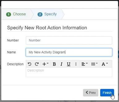
- Specify New Root Action Information
In step 2, you will be prompted to input a diagram ‘Name,’ ‘Number’ (optional), and ‘Description’ (optional). Then, click the ‘Finish’ button to save and automatically open your new Activity Diagram.
Activity Diagram Constructs
This section defines the building blocks of an ‘Activity Diagram’ in Innoslate. The ‘Activity Diagram’ supports seven unique diagram constructs:
- Entity
- Fork/Join (Parallel)
- Decision (Or)
- Decision (Loop)
- Branch Actor
- Guard
- Swimlane
-
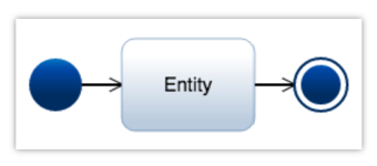
Entity
This construct is used to represent either an ‘Action’ or an ‘Activity.’ Where an ‘Action’ is a sub-part of an ‘Activity.’
In the system model, an Action entity is used to represent both ‘Action’ and ‘Activity’ with a decomposes/decomposed by relationship to the diagram’s root Activity. The Activity label is used to specify an Action as an ‘Activity.’ Other default database schema labels include Capability, Function, Mission, Process, Program, Project, Task, and/or Use Case.
In the diagram, this construct is represented as a rounded block containing the number and the name of the ‘Entity.’
-
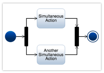
Fork/Join (Parallel)
This construct allows two or more ‘Entity’ constructs to perform simultaneously. Each thread of control is unique and they execute at the same time during the simulation. No changes are made to the system model in the database. In the diagram, the point where the arrow lines diverge from a vertical bar is the ‘Fork’ and the point where the arrow lines converge into a vertical bar is the ‘Join.’
-
Decision (Or)
This construct is used to represent a Decision Node followed by a Merge Node which has two or more potential control flow paths connecting the two, allowing an ‘Entity’ to be performed only under certain conditions. These two nodes have been combined into this single construct to ensure the model will execute. Each control flow path is unique and only one of the control flow paths will execute during simulation.
In the system model, an Action entity is used to represent a ‘Decision (Or)’ construct with a decomposes/decomposed by relationship to the diagram’s root Activity.
In the diagram, the ‘Decision’ is represented by a diamond-shaped block with arrow lines diverging from it, and the Merge is represented by a diamond-shaped block with arrow lines converging into it.

-
Decision (Loop)
This construct allows an ‘Entity’ construct or set of ‘Entity’ constructs to be repeated multiple times. During simulation, the number of iterations can be automated or you can be prompted for the number.
In the system model, an Action entity is used to represent a ‘Decision (Loop)’ construct with a decomposes/decomposed by relationship to the diagram’s root Activity.
In the diagram, this construct is represented as a diamond with two control flow outputs. The control flow to the right is repeated during simulation, while the control flow out of the bottom is the exit control flow.

-
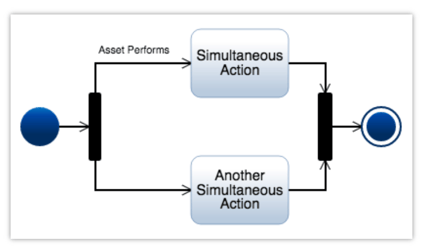
Branch Actor
This construct provides a way to visualize swim lanes by specifying who performs the actions on a particular ‘Fork/Join (Parallel)’ construct’s control flow path.
In the system model, an Asset entity is used to represent a ‘Branch Actor’ construct with a performs/performed by relationship to each of the Action entities (‘Entity’ constructs) on the ‘Fork/Join (Parallel)’ control flow path.
In the diagram, this construct is represented as a line label on a ‘Fork/Join (Parallel)’ construct’s control flow path, containing the name of the ‘Branch Actor.’
-
Blocked I/O (I/O Flow)
The ‘I/O (Flow)’ construct is used to represent what is allowed to “flow” from one ‘Entity’ construct (Action entity) to another ‘Entity’ construct (Action entity). The arrow on the ‘I/O (Flow)’ construct indicates the flow direction of ‘I/O (Flow)’. Attributes (properties) of ‘I/O (Flow)’ include Value, Type, Size, and Units.
In the system model, an ‘I/O (Flow)’ construct is related to ‘Entities’ (Action entities) with a generated by Action relationship with the origin Action entity, and a generates Action relationship with the destination Action entity.
An ‘I/O (Flow)’ construct is created when selecting a handle on one ‘Entity’ construct (‘Action’ entity, the “origin Action”) and dragging a line to a handle on another ‘Action’ entity (the “destination Action”). Successful creation of an ‘I/O (Flow)’ construct is indicated by a solid line terminated by small squares at each end of the ‘I/O (Flow)’ construct attached to both the origin Action entity and destination Action entity, with an arrow oriented toward the destination Action entity.
Control of “flow” associated with an ‘I/O (Flow)’ construct is accomplished via the Script assigned to the origin Action entity. In this way, the ‘I/O (Flow)’ construct acts as a Trigger when the associated ‘I/O (Flow)’ construct’s logic (including an assigned ‘Guard’ construct value, if any) is evaluated as “true”.

-
Swimlane
The ‘Swimlane’ construct is used to divide Activity diagrams into sections assigned to specific ‘Entity’ constructs (Action entities) and other constructs (e.g., ‘Fork/Join (Parallel)’, ‘Decision (Or)’, ‘Decision (Loop)’, ‘Branch Actor’, and ‘Guard’), and the associated functions, relationships, and any Script associated with those constructs.
The functionality of a Swimlane is accomplished via the performs Action relationship to the Activity diagram Action entities contained in the ‘Swimlane’.
A ‘Swimlane’ is oriented either as a vertical ‘Swimlane’ or a horizontal ‘Swimlane’. Horizontal Swimlanes are separated from adjacent horizontal Swimlanes by solid, horizontal lines on both the top and bottom sides of the horizontal Swimlane. Vertical Swimlanes are separated from other vertical Swimlanes by solid, vertical lines on both sides of the vertical Swimlane.

-
Guard
The ‘Guard’ construct is a textual “Guard Name” Attribute that is placed in an Activity diagram. The placed ‘Guard’ construct is not “attached” (i.e., unaffiliated) to any other constructs within the Activity diagram (i.e., it is a floating text field). The intended “functionality” of the ‘Guard’ construct within an Activity diagram is accomplished by incorporation of the ‘Guard’ construct’s “Guard Name” Attribute value within an intended construct’s function and/or Script.
‘Guard’ construct in the context of ‘Decision (Or)’ construct: The intent of the ‘Guard’ construct is to act as a “conditional statement” used to control the flow from a ‘Decision (Or)’ construct (i.e., Boolean Or expression). The ‘Guard’ construct’s conditions (i.e., outputs) are mutually exclusive of each other (e.g., in the diagram, Guard 1 is mutually exclusive of Guard 2). Flow from the ‘Decision (Or)’ construct to an Action entity is only possible if the associated ‘Guard’ construct is evaluated as “true”. Innoslate automatically assigns Guard 1 as “Yes” and Guard 2 as “No”, both of which are assigned via the Branch Name Attribute. These Branch Name Attributes can be edited as the user wishes.
‘Guard’ construct in the context of ‘I/O (Flow)’ construct: The intent of the ‘Guard’ construct is to act as a “conditional statement” used to control the flow through an ‘I/O (Flow)’ construct from one Action entity (’Entity’ construct) to another Action entity. Control of “flow” associated with an ‘I/O (Flow)’ construct is accomplished via the Script assigned to the origin Action entity. In this way, the ‘I/O (Flow)’ construct acts as a Trigger when the associated ‘I/O (Flow)’ construct’s logic (including an assigned ‘Guard’) is evaluated as “true”. In the diagram, flow from Action 1 to Action 2 is only possible if the Action 1 Script logic (including Guard 3) is evaluated as “true”.
‘Guard’ construct in the context of Activity diagram documentation: The ‘Guard’ construct can be used as a simple, unaffiliated text field anywhere within an Activity diagram for the purposes of labeling or documentation. In this case, the ‘Guard’ construct remains unaffiliated and without functionality.

Indicators
Scripting Indicator

Action Entities will now have an indicator to indicate scripting has been applied to it.
Adding an Entity
An ‘Entity’ construct can be added to an ‘Activity Diagram‘ via drag-and-drop.
- Within an ‘Activity Diagram,’ click the ‘Entity’ icon in the ‘New’ tab of the left sidebar and continue to hold down the left mouse button.
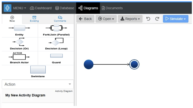
- Drag the ‘Entity’ icon over to the arrow line between the Start and End nodes.

- When the line between the Start and End nodes highlights green and the green ‘+’ appears, release the left mouse button to drop the new ‘Entity’ and add it to the diagram.

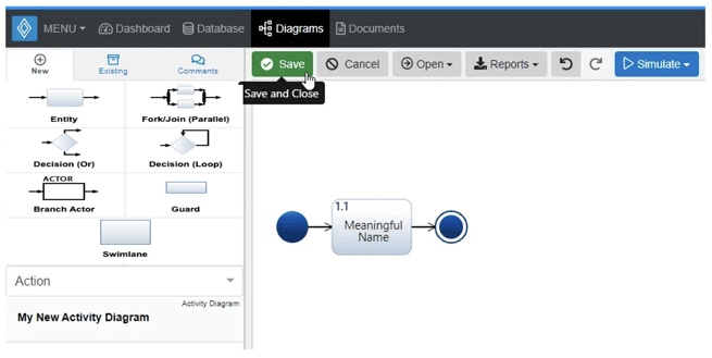
Notice the ‘Entity’ stays selected once it has been dropped. Since it is selected, the toolbar changes to include buttons for functions that can be used on the construct. The sidebar also changes to include additional ‘Metadata,’ ‘Attributes,’ and ‘Relationships’ tabs.
- Once added to the diagram, enter a meaningful ‘Name’ for your new ‘Entity’ via the ‘Attributes’ tab of the left sidebar (focused automatically for convenience).

- Click the ‘Save’ button located on the toolbar to persist your changes to your project’s database.
* Note: The above process describes using the ‘New’ tab of the left sidebar, which automatically generates a new entity to represent each new diagram construct. If you would like to reuse existing entities from your database to represent a new construct, use the ‘Existing’ tab instead.
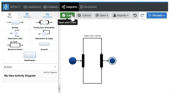
Adding a Fork/Join (Parallel)
A ‘Fork/Join (Parallel)’ construct can be added to an ‘Activity Diagram‘ via drag-and-drop.
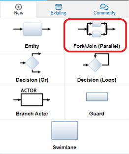
- Within an ‘Activity Diagram,’ click the ‘Fork/Join (Parallel)’ icon in the ‘New’ tab of the left sidebar and continue to hold down the left mouse button.
- Drag the ‘Fork/Join (Parallel)’ icon over to the arrow line between the Start and End nodes. When the line between the Start and End nodes highlights green and the green ‘+’ appears, release the left mouse button to drop the new ‘Fork/Join (Parallel)’ and add it to the diagram.
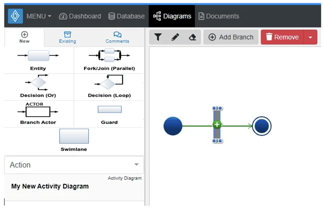
- Notice the ‘Fork/Join (Parallel)’ does not stay selected once it has been dropped. You can now begin to add other diagram constructs to the new control flow paths.
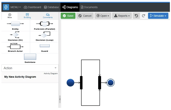
- Click the ‘Save’ button located on the toolbar to persist your changes to your project’s database.
Adding a Decision (OR)
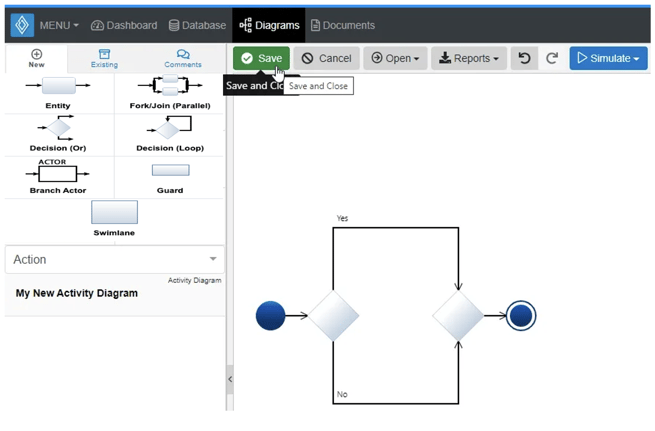
A ‘Decision (Or)’ construct can be added to an ‘Activity Diagram‘ via drag-and-drop.
- Within an ‘Activity Diagram,’ click the ‘Decision (Or)’ icon in the ‘New’ tab of the left sidebar and continue to hold down the left mouse button.

- Drag the ‘Decision (Or)’ icon over to the arrow line between the Start and End nodes.
When the line between the Start and End nodes highlights green and the green ‘+’ appears, release the left mouse button to drop the new ‘Decision(Or)’ and add it to the diagram.
Notice the ‘Decision (Or)’ stays selected once it has been dropped. Since it is selected, the toolbar changes to include buttons for functions that can be used on the construct. The sidebar also changes to include additional ‘Metadata,’ ‘Attributes,’ and ‘Relationships’ tabs.
- Once added to the diagram, enter a meaningful ‘Name’ for your new ‘Decision (Or)’ via the ‘Attributes’ tab of the left sidebar (focused automatically for convenience).

- Click the ‘Save’ button located on the toolbar to persist your changes to your project’s database.
* Note: The above process describes using the ‘New’ tab of the left sidebar, which automatically generates a new entity to represent each new diagram construct. If you would like to reuse existing entities from your database to represent a new construct, use the ‘Existing’ tab instead.
Adding a Decision (Loop)
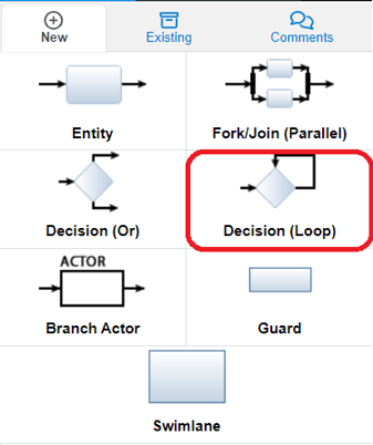
A ‘Decision (Loop)’ construct can be added to an ‘Activity Diagram‘ via drag-and-drop.
- Within an ‘Activity Diagram,’ click the ‘Decision (Loop)’ icon in the ‘New’ tab of the left sidebar and continue to hold down the left mouse button.
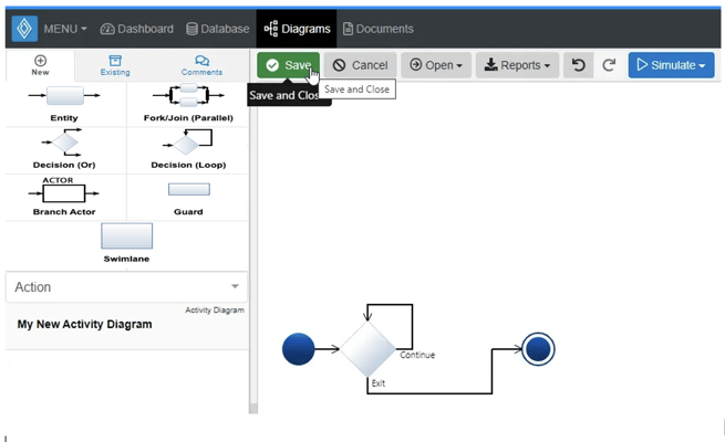
- Drag the ‘Decision (Loop)’ icon over to the arrow line between the Start and End nodes.
When the line between the Start and End nodes highlights green and the green ‘+’ appears, release the left mouse button to drop the new ‘Decision (Loop)’ and add it to the diagram.
Notice the ‘Decision (Loop)’ stays selected once it has been dropped. Since it is selected, the toolbar changes to include buttons for functions that can be used on the construct. The sidebar also changes to include additional ‘Metadata,’ ‘Attributes,’ and ‘Relationships’ tabs.
- Once added to the diagram, enter a meaningful ‘Name’ for your new ‘Decision (Loop)’ via the ‘Attributes’ tab of the left sidebar (focused automatically for convenience).

- Click the ‘Save’ button located on the toolbar to persist your changes to your project’s database.
* Note: The above process describes using the ‘New’ tab of the left sidebar, which automatically generates a new entity to represent each new diagram construct. If you would like to reuse existing entities from your database to represent a new construct, use the ‘Existing’ tab instead.
Adding a Branch Actor
A ‘Branch Actor’ construct can be added to an ‘Activity Diagram‘ via drag-and-drop. A ‘Fork/Join (Parallel)’ must first be added to the diagram before this construct can be added.
- Within an ‘Activity Diagram,’ click the ‘Branch Actor’ icon in the ‘New’ tab of the left sidebar and continue to hold down the left mouse button.

- Drag the ‘Branch Actor’ icon over to a branch of a ‘Fork/Join (Parallel)’ of your choice.

- When the branch highlights green, release the left mouse button to drop the new ‘Branch Actor’ and add it to the diagram.

Notice the ‘Branch Actor’ stays selected once it has been dropped. Since it is selected, the toolbar changes to include buttons for functions that can be used on the construct. The sidebar also changes to include additional ‘Metadata,’ ‘Attributes,’ and ‘Relationships’ tabs.
- Once added to the diagram, enter a meaningful ‘Name’ for your new ‘Branch Actor’ via the ‘Attributes’ tab of the left sidebar (focused automatically for convenience).

- Click the ‘Save’ button located on the toolbar to persist your changes to your project’s database.
Note: The above process describes using the ‘New’ tab of the left sidebar, which automatically generates a new entity to represent each new diagram construct. If you would like to reuse existing entities from your database to represent a new construct, use the ‘Existing’ tab instead.
Adding a Guard to an I/O Flow
A Guard can be placed via drag and drop on to the canvas. Below will go over adding a guard on an I/O Flow construct.
- To add a Guard to an I/O Flow within an ‘Activity Diagram,’ click the ‘Guard’ icon in the ‘New’ tab of the left sidebar and continue to hold down the left mouse button.

- Drag and drop the Guard construct next to the desired I/O construct.

3. As shown above, the left sidebar will change and allow users to name the Guard.
Adding a Guard to a Decision (Or)
It's important to note the Guard is already built into the Decision (Or) construct.
- Within an ‘Activity Diagram,’ click the ‘Decision (Or)’ icon in the ‘New’ tab of the left sidebar and continue to hold down the left mouse button.

- Drag the ‘Decision (Or)’ icon over to the arrow line between the Start and End nodes.
When the line between the Start and End nodes highlights green and the green ‘+’ appears, release the left mouse button to drop the new ‘Decision(Or)’ and add it to the diagram.

4. Once the construct is dropped onto the canvas, users may select the Guard on the branch and give it the desired name. Yes or No are the defaulted options.

Note, a Guard will also automatically appear, if more branches are added to the Decision construct. The Name on additional branches added is defaulted to Option.

Adding a Swimlane
- Within an ‘Activity Diagram,’ click the ‘Swimlane’ icon in the ‘New’ tab of the left sidebar and continue to hold down the left mouse button. Then drag and drop on to the canvas.

2. The left sidebar will then change so users may modfy it's name to their desire.
Note: Any actions already on the canvas that are within the swimlane or any action added into an already placed swimlane will auomatically create the performs/performed by relationship between the swimlane and action(s). This can be confirmed by clicking on the Action (or Swimlane) and its Relationships Tab on the left sidebar, as shown below.

Removing a Construct
A construct can be easily removed from an ‘Activity Diagram.’
- Within an ‘Activity Diagram,’ select the construct you wish to remove. This will make the toolbar appear with applicable functions which can be used on the selected construct.

- Click the ‘Remove’ button to remove the construct from the diagram (as the default action).

* Note: The ‘Remove’ button also includes a drop-down menu where you can select ‘Delete from Database’ or the default option of ‘Remove from Diagram.’
Simulating Activity Diagrams
- Within an ‘Activity Diagram‘ locate the ‘Simulate’ drop-down in the toolbar.
- Click to open the ‘Simulate’ drop-down and select either the ‘Monte Carlo’ or ‘Discrete Event’ menu item to be navigated to the respective simulation tool where you can simulate your model.

Tutorial Video
To continue learning about SysML Diagrams, Click Here.
(Next Article: Activity Diagram Modifications & Settings)