
Sections Available in this article:
Applying Time Distributions: An ‘Action’ construct can have its duration set using an upload Time Distribution file.
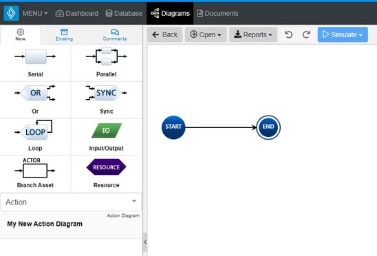
Action Diagram Constructs: The ‘Action Diagram’ supports eight unique diagram constructs: an ‘Action’, a ‘Parallel’, an ‘OR’, a ‘SYNC’, a ‘LOOP’, an ‘Input/Output’, a ‘Branch Asset’, and a ‘Resource.’
Adding a Serial: A ‘Serial’ construct can be added to an ‘Action Diagram’ via drag-and-drop.
Adding a Parallel: A ‘Parallel’ construct can be added to an ‘Action Diagram’ via drag-and-drop.
Adding an OR: An ‘OR’ construct can be added to an ‘Action Diagram’ via drag-and-drop.
Adding a SYNC: A ‘SYNC’ construct can be added to an ‘Action Diagram’ via drag-and-drop.
Adding a LOOP: A ‘LOOP’ construct can be added to an ‘Action Diagram’ via drag-and-drop.
Adding an Input/Output: An ‘Input/Output’ construct can be added to an ‘Action Diagram’ via drag-and-drop.
Adding a Branch Asset: A ‘Branch Asset’ construct can be added to an ‘Action Diagram’ via drag-and-drop.
Removing a Construct: A construct can be easily removed from an ‘Action Diagram.’
Simulating Diagrams: Within Sopatra, you can ‘Simulate Action Diagrams.’
The ‘Action Diagram’, which is traditionally known as an activity diagram or a functional flow diagram, is a method of displaying Action entities (and their subclasses such as Procedure), their interactions via Input/Output entities, and logic flow. This diagram conforms to the LML Specification 1.2 definition of an ‘Action Diagram’, which requires a diagram representation of the functional components of a system model.

Applying Time Distributions
Due to the complex nature of procedures within their environments, setting the duration Allowable Operational Time Windows (AOTW), Time of Procedures (ToP), or simple Events can be simplified using time distributions. After a time distribution file is imported and applied using the import analyzer, on an open diagram, select an Action entity to apply the proper time distribution to.
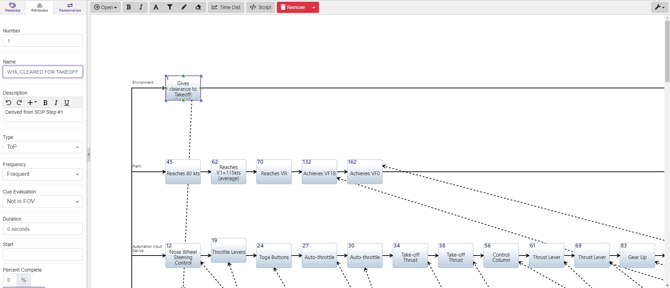
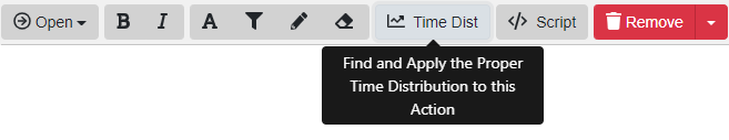
In the example above, a ToP Action entity was selected with an invalid duration set to 0 seconds. When an entity is selected, focus your attention on the toolbar and locate the button labeled Time Dist. Upon clicking it, the Time Distributions popup will appear.
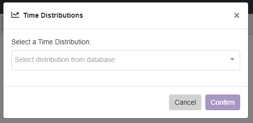
With the Time Distributions popup open, you may be able to find a dropdown allowing you to select a time distribution applicable to the selected entity. If no distributions appear, this can be a result of either not having an applicable time distribution in the time distribution file uploaded, your time distribution not being loaded, or simply never having uploaded one in the first place.
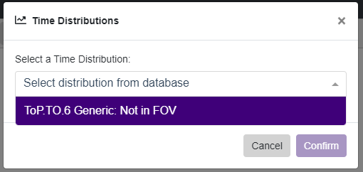
When a time distribution has been selected, a description of which action the time distribution will be applied to, its parameters as well as the duration to be set. If the settings are to your satisfaction, you can confirm them by clicking the Confirm button, otherwise, you may select another applicable time distribution or cancel altogether.
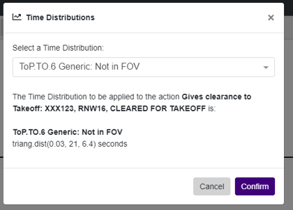
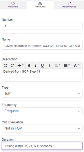
After clicking confirm, you can see the changes being made immediately in the attributes column of the selected entity with the duration attribute set to what was defined in the time distribution.
Action Diagram Constructs
The ‘Action Diagram’ supports eight unique diagram constructs: a ‘Serial’, a ‘Parallel’, an ‘OR’, a ‘SYNC’, a ‘LOOP’, an ‘Input/Output’, a ‘Branch Asset’, and a ‘Resource’. Each diagram construct is described in more detail below:
-
Serial
This construct is used to represent the classic systems engineering activity, function or task.
In the system model, an ‘Action’ entity is used to represent a ‘Serial’ construct with a decomposes/decomposed by relationship to the diagram’s root ‘Action’ entity. Innoslate‘s default database schema includes labels to specify the type of ‘Action’ entity as a(n) Activity, Capability, Function, Mission, Process, Program, Project, Task, and/or Use Case.
In the diagram, this construct is represented as a rounded block containing the number and name of the ‘Serial’ construct.
-
Parallel
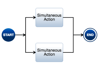
This construct allows two or more ‘Serial’ constructs to perform simultaneously. Each parallel branch is unique and all branches execute at the same time during the simulation. No changes are made to the system model in the database. In the diagram, the point where the arrow lines diverge is the start of the individual ‘Parallel’ branches and the point where the arrow lines converge is the end of the ‘Parallel’ branches.
-
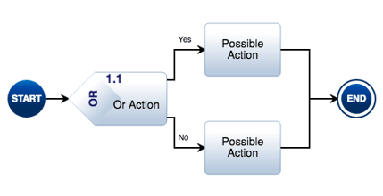
OR
This construct is used to represent a function that has two or more potential exit branches and allows ‘Serial’ constructs to be performed only under certain conditions. Each ‘OR’ exit branch is unique and only one of the many branches will execute during simulation.
In the system model, an Action entity is used to represent an ‘OR’ construct with a decomposes/decomposed by relationship to the diagram’s root Action entity. Innoslate‘s default database schema includes labels to specify the type of this Action entity as a(n) Activity, Capability, Function, Mission, Process, Program, Project, Task, and/or Use Case.
In the diagram, this construct is represented as a rounded block with a diamond shape entry point making up the left-hand side. This block contains the number and name of the ‘OR’. The point where the arrow lines diverge out from the right of the block is the start of the individual ‘OR’ exit branches and the point where the arrow lines converge is the end of the ‘OR’ exit branches.
-
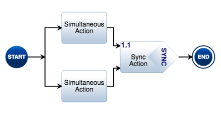
SYNC
This construct is used to control timeouts of the ‘Serial’ constructs inside the ‘SYNC’ construct’s parallel branches. Each parallel branch is unique and all branches execute at the same time during the simulation.
In the system model, an Action entity is used to represent a ‘SYNC’ construct with a decomposes/decomposed by relationship to the diagram’s root Action entity. Innoslate‘s default database schema includes labels to specify the type of this Action entity as a(n) Activity, Capability, Function, Mission, Process, Program, Project, Task, and/or Use Case.
In the diagram, this construct is represented as a rounded block with a diamond shape exit point making up the right-hand side. This block contains the number and name of the ‘SYNC’. The point where the arrow lines diverge is the start of the individual ‘SYNC’ branches and the point where the arrow lines converge back into the block is the end of the ‘SYNC’ branches.
-
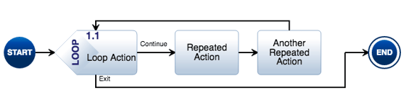
LOOP
This construct allows a ‘Serial’ construct or a set of ‘Serial’ constructs to be repeated multiple times. During a simulation, the number of ‘LOOP’ executions can be automated or you can be prompted for the number.
In the system model, an Action entity is used to represent a ‘LOOP’ construct with a decomposes/decomposed by relationship to the diagram’s root Action entity. Innoslate‘s default database schema includes labels to specify the type of this Action entity as a(n) Activity, Capability, Function, Mission, Process, Program, Project, Task, and/or Use Case.
In the diagram, this construct is represented as a rounded block with a diamond shape entry point making up the left-hand side. This block contains the number and name of the ‘LOOP’. The arrow line that points back to the top of the block is the ‘LOOP’ construct’s “Continue” branch and the arrow line leaving the bottom of the block is the ‘LOOP’ construct’s “Exit” branch.
-
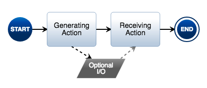
Input/Output
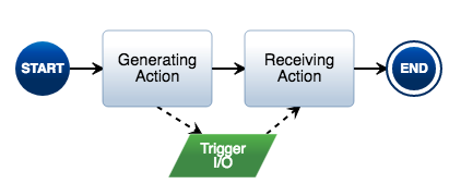
This construct is a functional representation of data that is passed between ‘Serial’ constructs.
In the system model, an Input/Output entity is used to represent an ‘Input/Output’ construct with at least one generated by/generates relationship to an Action entity representing a ‘Serial’ construct and at least one received by/receives relationship to another Action entity representing a ‘Serial’ construct in the diagram. The received by/receives relationship has an attribute named ‘Trigger’ which is used to specify whether the passed data is required before the next ‘Action’ can be performed or if it is optional. Innoslate‘s default database schema includes labels to specify the type of this Input/Output entity as Analog, Digital, Event, Mixed, Physical, Product, Response, and/or Verbal.
In the diagram, this construct is represented as either a bright green or a muted grey parallelogram with dashed arrow lines between itself and the ‘Serial’ constructs which have relationships to the ‘Input/Output’. If the ‘Trigger’ attribute is set to true on the received by/receives relationship, the ‘Input/Output’ will display as bright green, otherwise, if the ‘Trigger’ attribute is set to false, it will display as muted grey in the diagram.
-
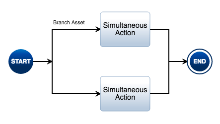
Branch Asset
This construct provides a way to visualize swim lanes by specifying who performs the functions on a particular ‘Parallel’ construct’s branch.
In the system model, an Asset entity is used to represent a ‘Branch Asset’ construct with a performs/performed by relationship to each of the Action entities representing the ‘Serial’ constructs on the ‘Parallel’ branch. Innoslate‘s default database schema includes labels to specify the type of this Asset entity as a(n) Architecture, Context, Environment, External System, Facility, Infrastructure, Materiale, Organization, Package, Personnel, Segment, Service, Subsystem, and/or System.
In the diagram, this construct is represented as a line label on a ‘Parallel’ branch, containing the name of the ‘Branch Asset’.
-
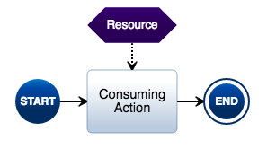
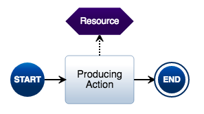
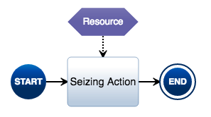
Resource
This construct provides a visual representation of a physical object that is consumed, produced, or seized by a function. The usage of each ‘Resource’ is monitored during the simulation and graphically displayed in the simulation results.
In the system model, a Resource entity is used to represent a ‘Resource’ construct with either a consumed by/consumes, produced by/produces or a seized by/seizes relationship to an Action entity representing a ‘Serial’ construct in the diagram.
In the diagram, this construct is represented as either a bright purple or a muted purple elongated hexagon with a dashed arrow line between itself and the ‘Serial’ construct which has relationships to the ‘Resource’. If the ‘Resource’ is consumed or produced, it will display as bright purple, otherwise, if the ‘Resource’ is seized, it will display as muted purple in the diagram.
A ‘Serial’ construct can be added to an ‘Action Diagram‘ via drag-and-drop.
- Within an ‘Action Diagram,’ click the ‘Serial’ icon in the ‘New’ tab of the left sidebar and continue to hold down the left mouse button.
- Drag the ‘Serial’ icon over to the arrow line between the Start and End nodes.
- When the line between the Start and End nodes is highlighted in green, release the left mouse button to drop the new ‘Serial’ and add it to the diagram.

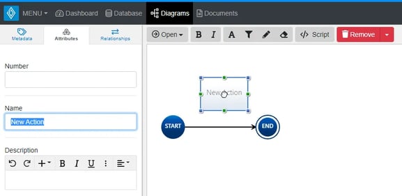
Note the ‘Serial’ stays selected once it has been dropped in place. Since it is selected, the toolbar changes to include buttons for functions that can be used on the construct. The sidebar also changes to include additional ‘Metadata,’ ‘Attributes’ and ‘Relationships’ tabs.
- Once added to the diagram, enter a meaningful ‘Name’ for your new ‘Serial’ via the ‘Attributes’ tab of the left sidebar (focused automatically for convenience).

- Click the ‘Save’ button located on the toolbar to persist your changes to your project’s database.

* Note: The above process describes using the ‘New’ tab of the left sidebar, which automatically generates a new entity to represent each new diagram construct. If you would like to reuse existing entities from your database to represent a new construct, use the ‘Existing’ tab instead.
For more information on this construct and how it is represented in the database model, see Action Diagram Constructs.
Adding a Parallel
A ‘Parallel’ construct can be added to an ‘Action Diagram‘ via drag-and-drop.
- Within an ‘Action Diagram,’ click the ‘Parallel’ icon in the ‘New’ tab of the left sidebar and continue to hold down the left mouse button.

- Drag the ‘Parallel’ icon over to the arrow line between the Start and End nodes.

- When the line between the Start and End nodes highlights green, release the left mouse button to drop the new ‘Parallel’ and add it to the diagram.

- The ‘Parallel’ does not remain selected once it has been dropped. You can now begin to add other diagram constructs to the new parallel branches.

- To add another branch, select the ‘Parallel’ construct, then select ‘Add Branch’ and you will see another branch appear. Add as many as desired by repeatedly clicking the button.

- Click the ‘Save’ button located on the toolbar to persist your changes to your project’s database.

* Note: For more information on this construct and how it is represented in the database model, see Action Diagram Constructs.
Adding an OR
An ‘Or’ construct can be added to an ‘Action Diagram‘ via drag-and-drop.
- Within an ‘Action Diagram’, click the ‘Or’ icon in the ‘New’ tab of the left sidebar and continue to hold down the left mouse button.

- Drag the ‘Or’ icon over to the arrow line between the Start and End nodes.

- When the line between the Start and End nodes highlights green, release the left mouse button to drop the new ‘Or’ and add it to the diagram.

Notice the ‘Or’ stays selected once it has been dropped. Since it is selected, the toolbar changes to include buttons for functions that can be used on the construct. The sidebar also changes to include additional ‘Metadata,’ ‘Attributes’ and ‘Relationships’ tabs.
- Once added to the diagram, enter a meaningful ‘Name’ for your new ‘Or’ via the ‘Attributes’ tab of the left sidebar (focused automatically for convenience).

- Click the ‘Save’ button located on the toolbar to persist your changes to your project’s database.

* Note: The above process describes using the ‘New’ tab of the left sidebar, which automatically generates a new entity to represent each new diagram construct. If you would like to reuse existing entities from your database to represent a new construct, use the ‘Existing’ tab instead.
For more information on this construct and how it is represented in the database model, see Action Diagram Constructs.
Adding a Sync
A ‘Sync’ construct can be added to an ‘Action Diagram‘ via drag-and-drop.
- Within an ‘Action Diagram,’ click the ‘Sync’ icon in the ‘New’ tab of the left sidebar and continue to hold down the left mouse button.

- Drag the ‘Sync’ icon over to the arrow line between the Start and End nodes.

- When the line between the Start and End nodes highlights green, release the left mouse button to drop the new ‘Sync’ and add it to the diagram.

Notice the ‘Sync’ stays selected once it has been dropped. Since it is selected, the toolbar changes to include buttons for functions that can be used on the construct. The sidebar also changes to include additional ‘Metadata,’ ‘Attributes’ and ‘Relationships’ tabs.
- Once added to the diagram, enter a meaningful ‘Name’ for your new ‘Sync’ via the ‘Attributes’ tab of the left sidebar (focused automatically for convenience).

- Click the ‘Save’ button located on the toolbar to persist your changes to your project’s database.

* Note: The above process describes using the ‘New’ tab of the left sidebar, which automatically generates a new entity to represent each new diagram construct. If you would like to reuse existing entities from your database to represent a new construct, use the ‘Existing’ tab instead.
For more information on this construct and how it is represented in the database model, see Action Diagram Constructs.
Adding a Loop
A ‘Loop’ construct can be added to an ‘Action Diagram‘ via drag-and-drop.
- Within an ‘Action Diagram’, click the ‘Loop’ icon in the ‘New’ tab of the left sidebar and continue to hold down the left mouse button.

- Drag the ‘Loop’ icon over to the arrow line between the Start and End nodes.

- When the line between the Start and End nodes highlights green, release the left mouse button to drop the new ‘Loop’ and add it to the diagram.

Notice the ‘Loop’ stays selected once it has been dropped. Since it is selected, the toolbar changes to include buttons for functions that can be used on the construct. The sidebar also changes to include additional ‘Metadata,’ ‘Attributes’ and ‘Relationships’ tabs.
- Once added to the diagram, enter a meaningful ‘Name’ for your new ‘Loop’ via the ‘Attributes’ tab of the left sidebar (focused automatically for convenience).

- Click the ‘Save’ button located on the toolbar to persist your changes to your project’s database.

* Note: The above process describes using the ‘New’ tab of the left sidebar, which automatically generates a new entity to represent each new diagram construct. If you would like to reuse existing entities from your database to represent a new construct, use the ‘Existing’ tab instead.
For more information on this construct and how it is represented in the database model, see Action Diagram Constructs.
Adding an Input/Output
An ‘Input/Output’ construct can be added to an ‘Action Diagram‘ via drag-and-drop.
- Within an ‘Action Diagram,’ click the ‘Input/Output’ icon in the ‘New’ tab of the left sidebar and continue to hold down the left mouse button.

- Drag the ‘Input/Output’ icon over to the adjacent diagram canvas.

- Release the left mouse button while over the diagram canvas to drop the new ‘Input/Output’ and add it to the diagram.

- Select the generating ‘Action’ construct, then click one of the green circles and continue to hold down the left mouse button.

- Drag the green circle to your newly created ‘Input/Output’ construct.

- When the ‘Input/Output’ highlights bright green, release the left mouse button to add a generated by/generates relationship.

- Select your newly created ‘Input/Output’ construct, then click one of the green circles and continue to hold down the left mouse button.

- Drag the green circle to the receiving ‘Action’ construct of your choice.

- When the receiving ‘Action’ highlights green, release the left mouse button to add the appropriate relationship. Releasing over the “Trigger” section will automatically add the received by/receives relationship with the Trigger relationship attribute set to “Yes,” while releasing over the “Optional” section will automatically add the received by/receives relationship with the Trigger relationship attribute set to “No.”

- Once added to the diagram with the proper relationship, enter a meaningful ‘Name’ for your new ‘Input/Output’ via the ‘Attributes’ tab of the left sidebar (focused automatically for convenience).

- Click on one of the lines. Position the lines by selecting the blue dots and moving them to the desired location around the shape.

- Click the ‘Save’ button located on the toolbar to persist your changes to your project’s database.

Note: The above process describes using the ‘New’ tab of the left sidebar, which automatically generates a new entity to represent each new diagram construct. If you would like to reuse existing entities from your database to represent a new construct, use the ‘Existing’ tab instead.
I/O Decomposition
Action diagrams’ ‘Input/Output’ parents now can support I/O decomposition which will display children ‘Input/Outputs’ and display the relationship between them when inside a decomposed Action diagram.
- Enter a decomposed Action diagram by clicking the ‘Decomposed’ button on a parent ‘Action’ in an Action diagram.

- Once inside the decomposed Action diagram, when a parent ‘Input/Outputs’ has children Input/Outputs, selecting the Parent ‘Input/Outputs’ will cause the ‘Decomposed Parent IO’ button to appear.

- Click on the ‘Decomposed Parent IO’ button to generate the Child ‘Input/Outputs.’

For more information on this construct and how it is represented in the database model, see Action Diagram Constructs.
Adding a Branch Asset
A ‘Branch Asset’ construct can be added to an ‘Action Diagram‘ via drag-and-drop.
- Within an ‘Action Diagram,’ with a Parallel construct already in place, click the ‘Branch Asset’ icon in the ‘New’ tab of the left sidebar and continue to hold down the left mouse button.

- Drag the ‘Branch Asset’ icon over to a branch of a ‘Parallel’ of your choice.

- When the branch highlights green and the green ‘+’ appears, release the left mouse button to drop the new ‘Branch Asset’ and add it to the diagram.

-
Notice the ‘Branch Asset’ stays selected once it has been dropped. Since it is selected, the toolbar changes to include buttons for functions that can be used on the construct. The sidebar also changes to include additional ‘Metadata,’ ‘Attributes’ and ‘Relationships’ tabs.
- Once added to the diagram, enter a meaningful ‘Name’ for your new ‘Branch Asset’ via the ‘Attributes’ tab of the left sidebar (focused automatically for convenience).

- Click the ‘Save’ button located on the toolbar to persist your changes to your project’s database.

* Note: The above process describes using the ‘New’ tab of the left sidebar, which automatically generates a new entity to represent each new diagram construct. If you would like to reuse existing entities from your database to represent a new construct, use the ‘Existing’ tab instead.
For more information on this construct and how it is represented in the database model, see Action Diagram Constructs.
Adding a Resource
A ‘Resource’ construct can be added to an ‘Action Diagram’ via drag-and-drop.
- Within an ‘Action Diagram,’ click the ‘Resource’ icon in the ‘New’ tab of the left sidebar and continue to hold down the left mouse button.

- Drag the ‘Resource’ icon over to the adjacent diagram canvas.

- Release the left mouse button while over the diagram canvas to drop the new ‘Resource’ and add it to the diagram.

Note the ‘Resource’ stays selected once it has been dropped in place. Since it is selected, the toolbar changes to include buttons for functions that can be used on the construct. The sidebar also changes to include additional ‘Metadata,’ ‘Attributes’ and ‘Relationships’ tabs. - With the ‘Resource’ selected, green dots on the top, left, bottom, and right are shown. Click one of the green circles and continue to hold down the left mouse button.

- Drag the green circle to the destination ‘Action’ of your choice.

- When the destination ‘Action’ highlights purple, release the left mouse button to add the appropriate relationship. Releasing over the “Consumes” section will automatically add the consumed by/consumes relationship, while releasing over the “Seizes” section will automatically add the seized by/seizes relationship.
- Once added to the diagram with the proper relationship, enter a meaningful ‘Name’ for your new ‘Resource’ via the ‘Attributes’ tab of the left sidebar (focused automatically for convenience).

- Click on one of the lines. Position the lines by selecting the blue dots and moving them to the desired location around the shape.

- Click the ‘Save’ button located on the toolbar to persist your changes to your project’s database.

* Note: The above process describes using the ‘New’ tab of the left sidebar, which automatically generates a new entity to represent each new diagram construct. If you would like to reuse existing entities from your database to represent a new construct, use the ‘Existing’ tab instead.
For more information on this construct and how it is represented in the database model, see Action Diagram Constructs.
Removing a Construct
A construct can be easily removed from an ‘Action Diagram.’
- Within an ‘Action Diagram,’ select the construct you wish to remove. This will make the toolbar appear with applicable functions which can be used on the selected construct.

- Click the ‘Remove’ button to remove the construct from the diagram (as the default action).

* Note: The ‘Remove’ button also includes a drop-down menu where you can select ‘Delete from Database’ or the default option of ‘Remove from Diagram.’
Simulating Action Diagrams
- Within an ‘Action Diagram‘ locate the ‘Simulate’ drop-down in the toolbar.

- Click to open the ‘Simulate’ drop-down and select either the ‘Monte Carlo‘ or ‘Discrete Event‘ menu item to be navigated to the respective simulation tool where you can simulate your model.

To continue learning about Sopatra Diagrams, Click Here.
(Next Article: Generate Diagram Reports)