
The previous article on the Requirements Diagram provides users with an introductory explanation of the constructs and their functionality on the canvas. In the following section, we will delve into more detail about the options available for the canvas constructs and the toolbar options provided for each construct.
| Block Construct Editing | A review of the editing options for the Block Construct. |
| Line Construct Editing | A review of the editing options for the Line Construct. |
| Multiple Constructs Editing | A review of the editing options when multiple constructs are selected. |
| Requirements Diagram Settings | A review of the settings options for the Requirements Diagram. |
Block Construct Editing
When a Block construct is selected on the canvas the top of the toolbar frame changes, as highlighted below, for users to modify it's appearance on the canvas.

Below, we will provide an explanation of each option that is highlighted in the image above.
Users may Bold the name and all the text in the Block construct selected on the canvas.

This option will Italicize the name and all the text in the Block construct selected on the canvas.

Using the Color Window that drops down from the 'Change Stroke/Line Color Option', users can change the color that borders the Block construct selected on the canvas.

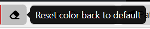
The Reset color back to default option will change the Block construct selected on the canvas back to the default gray and black colors.
Line Construct Editing

When a line construct is selected on the canvas the top of the toolbar frame changes, as highlighted above, for users to modify it's appearance on the canvas. Below we will cover each option available.
![]()
Note, the circled plus construct is on the parent entity indicating its connected to a child.
Users may change the color of the line and the circled plus (if included) with this option.
This option will set the line back to the defaulted black.

If orthogonal, users may change the selected line on the canvas to straight, or back to orthogonal if the line is straight.
Multiple Entities Editing

Users may select multiple constructs on the canvas by clicking and dragging their cursor outside of the constructs where a box will start to appear allowing them to select as many entities as they desire. In this case, users have the option to change the appearance of these entities all at once. It's important to note that when selecting multiple entities, only the Blocks will be modified.
This option will 'Bold' the text in the Block constructs selected on the canvas.

This option will 'Italicize' the text in the Block constructs selected on the canvas.

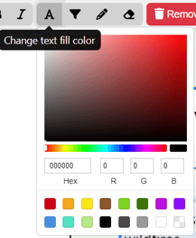
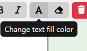
Using the Color Window the that drops down from the Fill Color Option, users can change the color of the Block selected on the canvas. the Text Fill Color Option, users can change the text color of the construct selected on the canvas by selecting the color using the Hex, R, G, B fields with the proper codes and numbers.
 Using the Color Window the that drops down from the Text Fill Color Option, users can change the color of the multiple constructs selected on the canvas.

Using the Color Window that drops down from the Change Stroke/Line Color Option, users can change the color that borders the constructs selected on the canvas.

The Reset color back to default option will change the construct and text on the canvas back to the default gray and black colors.
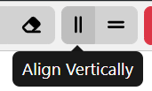
This option will align the constructs vertically selected on the canvas. An entity will turn green and that is where the vertical layout will start.
 This option will align the constructs horizontally selected on the canvas. An entity will turn green and that is where the horizontal layout will start.
Requirements Diagram Settings
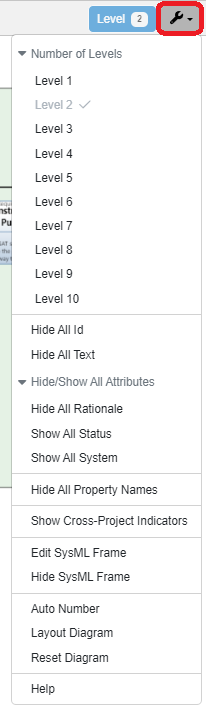 The wrench icon is a fixed dropdown at the top right of the toolbar frame for more settings and options for users to utilize. Below we will cover all of them for the Requirements Diagram.
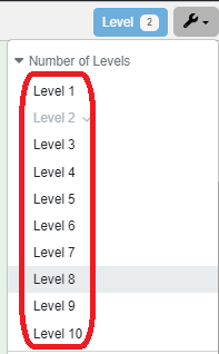
The settings dropdown provides users the option to display up to 10 levels of decomposition in a Requirements Diagram. Note the blue box next to the wrench icon, indicates how many levels are selected and displayed in the diagram for convenience.
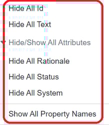
Users have the ability to hide, or show, all of the highlighted attributes in the block constructs. Below we will cover each attribute as is on the dropdown menu.
- Id: The entity's Number field
- All Text: The entity's Description field
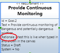
- Property Name: The attribute's name before the test, as indicated in the image below.
- Rationale: The Requirement's Rationale attribute.
- Status: The Requirement's Status attribute.
- System: The Requirement's System attribute.
![]()
If using Cross-Project Relationships, users may show or hide indicators on the entities being pulled in from other projects.
⚠️The SySML Frame is the green space the model is placed in on the canvas.

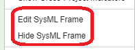
The Edit SysML Frame option will bring up the following window.

Users may select the color of the frame with the Color option![]() (the color on the button will change to whatever color a user sets it to). Users may also bring the SysML frame back to the defaulted green with the Reset option
(the color on the button will change to whatever color a user sets it to). Users may also bring the SysML frame back to the defaulted green with the Reset option ![]() .
.
The additional options on the modal are related to the text displayed at the top left of the SysML frame, as shown in the example below.
![]()
The changes made to the Select SysML Diagram option in the Modal refer to the Model Element Type text in the first brackets (ex. [Package] in the picture above). Note, the example above is from a Requirements Diagram but shows the Package option. Therefore it is important to note, users may select a different digram type here, even if you're in a different diagram. The text will change but this option will not change the diagram itself.
The Select Parent option is a dropdown to select the Parent entity for the Model Element Name. This will only change the text in between the bracketed texts. In the example above it is the 'Battery GSE Charge Display' text.
Users may use this option to hide or show the SysML Frame as they wish.
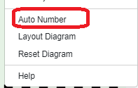
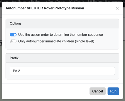
Users may also Auto Number their diagrams, where a pop up shows up to allow users to provide a Prefix or enumerate the single level, as shown below.
Lastly, the final options provide users to reset their diagram and layout the diagram fro previous changes made.
The very last option, 'Help,' will send users directly to the Help Center page for the Requirements Diagram for convenience.

Frame Fix
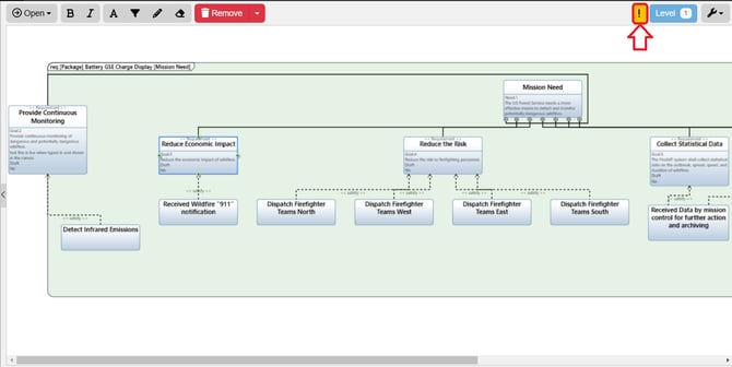
When a construct is outside of the SysML Frame, Innoslate will detect that and bring up a fix for this as indicated with the orange exclamation point that appears next to the Settings dropdown. When selected, a window pops up to provide users the ability to fix or ignore the issue.

To continue learning about SysML Diagrams, Click Here.
(Next Article: Sequence Diagram)