
Using Sequence Diagrams
| Function | Description |
|---|---|
| Creating Sequence Diagrams | Using ‘Diagrams View’ in Innoslate, you can create a new ‘Sequence Diagram.’ |
| Sequence Diagram Constructs | The ‘Sequence Diagram’ supports two unique diagram constructs: a ‘Lifeline’ and a ‘Message.’ |
| Adding a Lifeline | A ‘Lifeline’ construct can be added to a ‘Sequence Diagram’ via drag-and-drop. |
| Adding a Message | A ‘Message’ construct can be added to a ‘Sequence Diagram’ via drag-and-drop. |
| Removing a Construct | A construct can be easily removed from a ‘Sequence Diagram.’ |
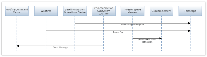
The ‘Sequence Diagram’ is used to represent the sequential message flow (Action entities) between Lifelines (Asset entities). The diagram is represented in standard SysML and LML notation and is bidirectionally compatible with the Action diagram.
In order for the Actions to appear in the Sequence Diagram, the Action must have the 'generating' Relationship to an Input/Output as well as the 'Trigger' Relationship Attribute to 'Yes'.
Creating Sequence Diagrams
Within the ‘Diagrams Dashboard,’ users can create a new diagram by clicking the ‘ Create Diagram’ button in the top right corner of the page.
.webp?width=670&name=create_activity-2-1536x776%20(1).webp)
Clicking the ‘ Create Diagram’ button will open the Create Diagram dialog where you will be directed through the process of creating a new diagram.
Create a Sequence Diagram
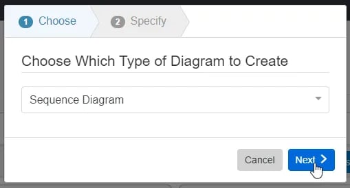
- Choose Which Type of Diagram to Create
In step 1, select ‘Sequence Diagram,’ under ‘SysML,’ as your diagram type.

Click the ‘Next’ button.
- Specify New Root Action Information
In step 2, you will be prompted to input a diagram ‘Name,’ ‘Number’ (optional), and ‘Description’ (optional). Then, click the ‘Finish’ button to save and automatically open your new Sequence Diagram.

Sequence Diagram Constructs
This section defines the building blocks of a ‘Sequence Diagram’ in Innoslate. The ‘Sequence Diagram’ supports two unique diagram constructs: a ‘Lifeline’ and a ‘Message.’ Each diagram construct is described in more detail below:
-
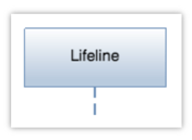
Lifeline
This construct is used to capture the physical components of a system that are interacting with each other.
In the system model, an Asset entity is used to represent a ‘Lifeline’ construct. Innoslate’s default database schema includes labels to specify the type of this Asset entity as a(n) Architecture, Context, Environment, External System, Facility, Infrastructure, Materiale, Organization, Package, Personnel, Segment, Service, Subsystem, and/or System.
In the diagram, this construct is represented as a rectangle shape containing the name of the ‘Lifeline’ with a dashed vertical line centered below it.
-
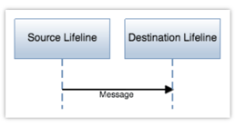
Message
In the context of Sequence Diagrams, the 'Message' construct represents interactions between 'Lifeline' entities. These interactions are carried out by 'Actions,' which are processes that facilitate the exchange of inputs and outputs between 'Lifelines.' To be included in the Sequence Diagram, these 'Actions' must have a generating relationship along with its Relationship Attribute 'Trigger' set to 'Yes.'
In the diagram, this construct is represented as an arrow pointing to a destination ‘Lifeline’ which originates from a source ‘Lifeline,’ and a line label containing the name of the ‘Message.’
Adding a Lifeline
A ‘Lifeline’ construct can be added to a ‘Sequence Diagram’ via drag-and-drop.
-
Within a ‘Sequence Diagram’, click the ‘Lifeline (Asset)’ icon in the ‘New’ tab of the left sidebar and continue to hold down the left mouse button.

-
Drag the ‘Lifeline (Asset)’ icon over to the adjacent diagram canvas.

-
Release the left mouse button while over the diagram canvas to drop the new ‘Lifeline’ and add it to the diagram. The ‘Lifeline’ will automatically snap to the position at the top of the diagram, ordered by number.

Notice the ‘Lifeline’ stays selected once it has been dropped. Since it is selected, the toolbar changes to include buttons for functions that can be used on the construct. The sidebar also changes to include additional ‘Metadata,’ ‘Attributes,’ and ‘Relationships’ tabs.
-
Once added to the diagram, enter a meaningful ‘Name’ for your new ‘Lifeline’ via the ‘Attributes’ tab of the left sidebar (focused automatically for convenience).

-
Click the ‘Save’ button located on the toolbar to persist your changes to your project’s database.

* Note: The above process describes using the ‘New’ tab of the left sidebar, which automatically generates a new entity to represent each new diagram construct. If you would like to reuse existing entities from your database to represent a new construct, use the ‘Existing’ tab instead.
Adding a Message
A ‘Message’ construct can be added to a ‘Sequence Diagram’ via drag-and-drop.
-
Within a ‘Sequence Diagram’, select the source ‘Lifeline’ where you would like the ‘Message’ to originate from.

-
Click the green circle and continue to hold down the left mouse button.

-
Drag the green circle to the dashed line below the destination ‘Lifeline’ of your choice.

-
When the dashed line below the destination ‘Lifeline’ highlights green, release the left mouse button to drop the new ‘Message’ and add it to the diagram.

Notice the ‘Message’ stays selected once it has been dropped. Since it is selected, the toolbar changes to include buttons for functions that can be used on the construct. The sidebar also changes to include additional ‘Metadata,’ ‘Attributes,’ and ‘Relationships’ tabs.
-
Once added to the diagram, select your new ‘Message’ and enter a meaningful ‘Name’ for your ‘Message’ via the ‘Attributes’ tab of the left sidebar.

-
Click the ‘Save’ button located on the toolbar to persist your changes to your project’s database.

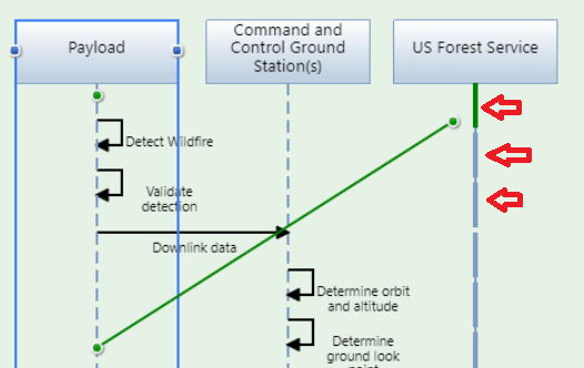
It's important to point out, when adding messages they are automatically placed in sequential order. If you need to add a new lifeline in a different position, you can simply drag the message and drop it to the desired spot on the receiving lifeline with the dashed lines, as indicated in the image below.
Note: The above process describes using the ‘New’ tab of the left sidebar, which automatically generates a new entity to represent each new diagram construct. If you would like to reuse existing entities from your database to represent a new construct, use the ‘Existing’ tab instead.
Removing a Construct
A construct can be easily removed from a ‘Sequence Diagram.’
- Within a ‘Sequence Diagram,’ select the construct you wish to remove. This will make the toolbar appear with applicable functions which can be used on the selected construct.

- Click the ‘Remove’ button to remove the construct from the diagram (as the default action).

* Note: The ‘Remove’ button also includes a drop-down menu where you can select ‘Delete from Database’ or the default option of ‘Remove from Diagram.’
Tutorial Video
To continue learning about SysML Diagrams, Click Here.
(Next Article: Sequence Diagram Modifications & Settings)