
Using Physical I/O Diagrams
| Function | Description |
|---|---|
| Creating Physical I/O Diagrams | Using ‘Diagrams View’ in Innoslate, you can create a new ‘Physical I/O Diagram.’ |
| Physical I/O Diagram Constructs | The ‘Physical I/O Diagram’ supports two unique diagram constructs: an ‘Asset’ and an ‘Input/Output.’ |
| Adding an Asset | An ‘Asset’ construct can be added to a ‘Physical I/O Diagram’ via drag-and-drop. |
| Adding an Input/Output | An ‘Input/Output’ construct can be added to a ‘Physical I/O Diagram’ via drag-and-drop. |
| Removing a Construct | A construct can be easily removed from a ‘Physical I/O Diagram.’ |
| Repair the Diagram | How to repair the connections to the I/O. |
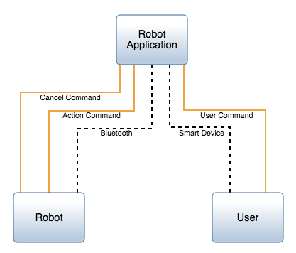
The ‘Physical I/O Diagram’ is a cross-over diagram, which displays the functional interactions and relationships between the physical components of a system model.
Creating Physical I/O Diagrams
Within the ‘Diagrams Dashboard,’ users can create a new diagram by clicking the ‘ New Diagram’ button in the top right corner of the page.
-1.webp?width=670&name=create_activity-2%20(1)-1.webp)
Clicking the ‘ New Diagram’ button will open the New Diagram dialog where you will be directed through the process of creating a new diagram.
Create a Physical I/O Diagram
1. Choose Which Type of Diagram to Create
In step 1, select ‘Physical I/O Diagram,’ under ‘LML,’ as your diagram type.

2. Click the ‘Next’ button.

3. Specify New Root Action Information
In step 2, you will be prompted to input a diagram ‘Name,’ ‘Number’ (optional), and ‘Description’ (optional). Then, click the ‘Finish’ button.

Physical I/O Constructs
The ‘Physical I/O Diagram’ supports two unique diagram constructs: an ‘Asset’ and an ‘Input/Output.’ Each diagram construct is described in more detail below:
-
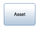
Asset
This construct is used to capture the physical components of a system.
In the system model, a simple Asset entity is generated to represent an ‘Asset’ construct with no additional diagram-specific information. Innoslate’s default database schema includes labels to specify the type of this Asset entity as a(n) Architecture, Context, Environment, External System, Facility, Infrastructure, Materiale, Organization, Package, Personnel, Segment, Service, Subsystem, and/or System.
In the diagram, this construct is represented as a rounded block containing the number and name of the ‘Asset.’
-
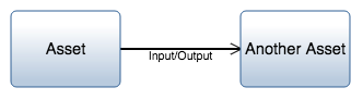
Input/Output
This construct is a functional representation of data that is passed between ‘Action’ constructs through a ‘Conduit’ connected between ‘Assets.’
In the system model, an Input/Output entity is used to represent an ‘Input/Output’ construct with at least one generated by/generates relationship to an Action entity representing an ‘Action’ construct and at least one received by/receives relationship to another Action entity representing an ‘Action’ construct in the diagram. The Input/Output is transferred over a ‘Conduit,’ through the transferred by relationship. The Conduit connects to two Assets which are displayed on the Physical I/O Diagram. Innoslate’s default database schema includes labels to specify the type of this Input/Output entity as Analog, Digital, Event, Mixed, Physical, Product, Response, and/or Verbal.
In the diagram, this construct is represented as a solid directional line connecting two ‘Asset’ constructs and a line label containing the name of the ‘Input/Output.’
An ‘Asset’ construct can be added to a ‘Physical I/O Diagram‘ via drag-and-drop.
- Within a ‘Physical I/O Diagram,’ click the ‘Asset’ icon in the ‘New’ tab of the left sidebar and continue to hold down the left mouse button.

- Drag the ‘Asset’ icon over to the adjacent diagram canvas.

- Release the left mouse button while over the diagram canvas to drop the new ‘Asset’ and add it to the diagram.

Notice the ‘Asset’ stays selected once it has been dropped. Since it is selected, the toolbar changes to include buttons for functions that can be used on the construct. The sidebar also changes to include additional ‘Metadata,’ ‘Attributes’ and ‘Relationships’ tabs.
- Once added to the diagram, enter a meaningful ‘Name’ for your new ‘Asset’ via the ‘Attributes’ tab of the left sidebar (focused automatically for convenience).

- Click the ‘Save’ button located on the toolbar to persist your changes to your project’s database.

* Note: The above process describes using the ‘New’ tab of the left sidebar, which automatically generates a new entity to represent each new diagram construct. If you would like to reuse existing entities from your database to represent a new construct, use the ‘Existing’ tab instead.
Adding an Input/Output
An ‘Input/Output’ construct can be added to a ‘Physical I/O Diagram’ via drag-and-drop. The example used on this page connects two ‘Asset’ constructs with an ‘Input/Output’ construct.
- Within a ‘Physical I/O Diagram,’ select the ‘Asset’ you would like connected to another ‘Asset.’

- Click one of the green circles on the selected ‘Asset’ and continue to hold down the left mouse button.

- Drag the green circle over to another ‘Asset’ of your choice.

- When the other ‘Asset’ box highlights green, release the left mouse button to drop the new ‘Input/Output’ and add it to the diagram.

- This opens the ‘New Input/Output Creation’ dialog.
.webp?width=407&height=535&name=add_io_pio_step5%20(1).webp)
- You will be asked to select the ‘Conduit,’ ‘Asset’s Action,’ and ‘Another Asset’s Action’ using drop-down menus. Next to ‘Select Conduit,’ click the blue ‘Create’ button (for the default action of creating a new conduit), or click the drop-down arrow to select an ‘Existing Entity’ or the ‘Create Conduit’ (default action).
.webp?width=407&height=535&name=add_io_pio_step6%20(1).webp)
- Depending on your previous choice, either select your ‘Existing Entity’ or give your new ‘Conduit’ a ‘Name’ and fill in any other meaningful details. Click the green checkmark button to save your selection.
.webp?width=422&height=694&name=add_io_pio_step7%20(1).webp)
Repeat the same selection process for ‘Select Asset’s Action’ and ‘Select Another Asset’s Action.’
- Make your selections for ‘Directionality’ and ‘Origin.’
.webp?width=380&height=501&name=add_io_pio_step8%20(1).webp)
- Click the green ‘Create’ button at the bottom of the dialog to create your new ‘Input/Output’ construct.
.webp?width=378&height=498&name=add_io_pio_step9%20(1).webp)
- Once added to the diagram, notice the ‘Input/Output’ stays selected once it has been dropped. Since it is selected, the toolbar changes to include buttons for functions that can be used on the construct. The sidebar also changes to include additional ‘Metadata,’ ‘Attributes’ and ‘Relationships’ tabs.
- Enter a meaningful ‘Name’ for your new ‘Input/Output’ via the ‘Attributes’ tab of the left sidebar (focused automatically for convenience).
.webp?width=670&name=add_io_pio_step11%20(1).webp)
- Click the ‘Save’ button located on the toolbar to persist your changes to your project’s database.
.webp?width=670&name=add_io_pio_step12%20(1).webp)
Removing a Construct
A construct can be easily removed from a ‘Physical I/O Diagram.’
- Within a ‘Physical I/O Diagram,’ select the construct you wish to remove. This will make the toolbar appear with applicable functions which can be used on the selected construct.

- Click the ‘Remove’ button to remove the construct from the diagram (as the default action).

* Note: The ‘Remove’ button also includes a drop-down menu where you can select ‘Delete from Database’ or the default option of ‘Remove from Diagram.’
Repair a Physical I/O Diagram

As users build or open their models into the Physical I/O diagram, users may notice their I/O lines may be dashed, yellow or red. These indicate issues to the I/O for the user to repair. Upon selecting one of these lines, users may select the repair button on the top of the toolbar frame so the Repair Modal comes up so users may fix the issues. Below goes over the issues with the different line color or appearance indicators
- A yellow line means there is a missing relationship to the I/O. Either a Conduit and/or actions are missing.
- A dash line indicates it is a conduit and it needs an I/O relationship that the Conduit transfers. Upon this fix, the line will be the I/O entity.
- A red line indicates there is an issue with the directionality of the I/O between the Assets.
To continue learning about General Diagrams, Click Here.
(Next Article: Physical I/O Modifications & Settings)