
Using Interface Control Diagram
|
Function |
Description |
|
Using ‘Diagrams View’ in Innoslate, you can create a new ‘Interface Control Diagram’. |
|
|
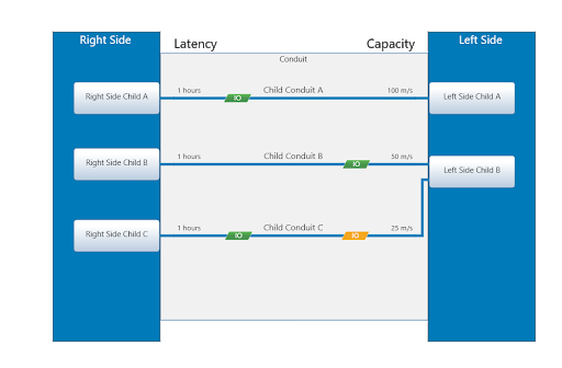
The ‘Interface Control Diagram’ supports four unique diagram constructs: an ‘Asset’, ‘Input/Output’, ‘Conduit’, and Parent Asset. |
|
|
A Parent ‘Asset’ construct can be added to an ‘Interface Control Diagram’ via selecting an ‘Asset’ in the left and right parent panel below the Interface Control Diagram name panel. |
|
|
An Existing Parent ‘Asset’ construct can be added to an ‘Interface Control Diagram’ via the left sidebar. |
|
|
A Child ‘Asset’ construct can be added to an ‘Interface Control Diagram’ via drag-and-drop. |
|
|
A Child ‘Conduit’ construct can be added to an ‘Interface Control Diagram’ via drag-and-drop. |
|
|
An ‘Input/Output’ construct can be added to an ‘Interface Control Diagram’ via drag-and-drop. |
|
|
A construct can be easily removed from an ‘Interface Control Diagram’. |
The ‘Interface Control Diagram’ is a way to define an interface decomposition between two systems.
Creating Interface Control Diagram
Within the ‘Diagrams Dashboard,’ users can create a new diagram by clicking the ‘Create Diagram’ button in the top right corner of the page.
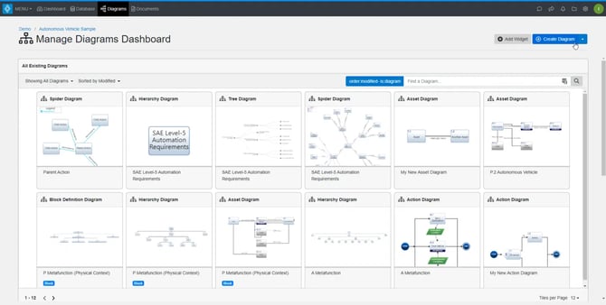
Clicking the ‘ Create Diagram’ button will open the Create Diagram dialog where you will be directed through the process of creating a new diagram.
Create an Interface Control Diagram
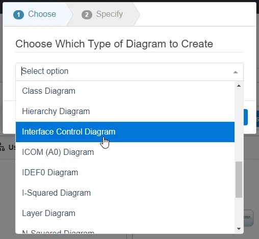
- Choose Which Type of Diagram to Create
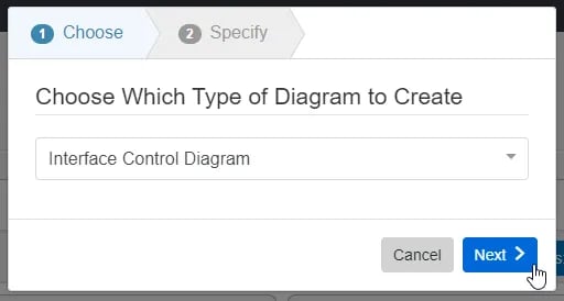
In step 1, select ‘Interface Control Diagram,’ under ‘General,’ as your diagram type.
Click the ‘Next’ button.
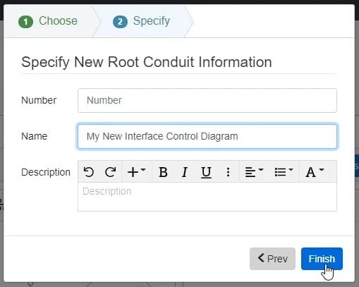
- Specify New Root Action Information
In step 2, you will be prompted to input a diagram ‘Name,’ ‘Number’ (optional), and ‘Description’ (optional). Then, click the ‘Finish’ button to save and automatically open your new Interface Control Diagram.
Interface Control Diagram Constructs
The ‘Interface Control Diagram’ supports four unique diagram constructs: a Parent ‘Asset’, Child ‘Asset’, Child ‘Conduit’, and ‘Input/Output’. Each diagram construct is described in more detail below:
Asset
This construct is used to capture the physical components of a system.
In the system model, a simple Asset entity is generated to represent an ‘Asset’ construct with no additional diagram-specific information. Innoslate’s default database schema includes labels to specify the type of this Asset entity as a(n) Architecture, Block, Context, Environment, External System, Facility, Infrastructure, Materiale, Organization, Package, Personnel, Segment, Service, Subsystem, and/or System.
In the diagram, the parent construct is represented as a blue block containing the number and name of the Parent ‘Asset.’ The child construct is represented as a rounded block containing the number and name of the ‘Asset.’ Parent constructs can be displayed two at a time in the ‘Interface Control Diagram’.
Parent Asset Construct & Child Asset Construct

Conduit
This construct is used to capture the relationships between the physical components of a system.
In the system model, a Conduit entity is generated to represent a ‘Conduit’ construct with the “connects to” relationship to each of the entities which represent the two connected constructs. Innoslate’s default database schema includes labels to specify the type of this Conduit entity as a(n) Aggregation, Association, Cable, Composition, Downlink, Interface, Network, Pipe, Roadway, Uplink, and/or Wireless.
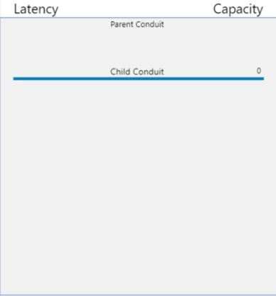
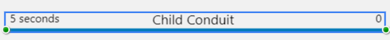
In the diagram, this root construct is represented as a gray box and the child conduit is represented as a solid blue line and a line label containing the name of the Conduit. The line can then be connected to child or parent ‘Asset’ constructs. The Latency and Capacity number attributes are also shown on the line. Latency is on the left and Capacity is on the right.
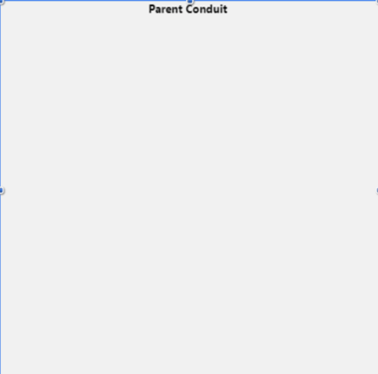
Parent Conduit Construct
Child Conduit Construct
Input/Output
![]()
This construct is a functional representation of data that is passed between ‘Action’ constructs through a ‘Conduit’ connected between ‘Assets’.
In the system model, an Input/Output entity is used to represent an ‘Input/Output’ construct with at least one generated by/generates relationship to an Action entity representing an ‘Action’ construct and at least one received by/receives relationship to another Action entity representing an ‘Action’ construct in the diagram. The Input/Output is transferred over a ‘Conduit’, through the transferred by relationship. Innoslate’s default database schema includes labels to specify the type of this Input/Output entity as Analog, Digital, Event, Mixed, Physical, Product, Response, and/or Verbal.
In the diagram, this construct is represented as a solid green parallelogram the name of the Input/Output. A child ‘Conduit’ must be present to attach ‘Input/Output’ to the diagram.
Adding a New Parent Asset

1. Parent ‘Asset’ construct can be added to an ‘Interface Control Diagram’ via clicking on the New Parent Asset button located on the top toolbar frame. Note, a Parent ‘Asset’ must be added to the diagram first before any Child ‘Asset’ constructs can be added.
2. Upon clicking on the button, a modal will pop up allowing users to create the new Parent Asset:
3. On the Modal, users can create the entity with the 'Create' button. More fields will appear to give the new Parent Asset a number, name and description.
4. The choice as to what side of the Parent Conduit for it to appear will also be in this Modal.
5. After selecting the side, be sure to click on the green check mark to save the new Parent Asset.

6. After clicking on the green checkmark, the blue create button will allow it to appear on the diagram.

Adding an Existing Parent Asset
An existing Parent ‘Asset’ construct can be added to an ‘Interface Control Diagram’ via clicking on and selecting an asset from the left or right parent asset panel shown below. A Parent ‘Asset’ must be added to the diagram first before any Child ‘Asset’ constructs can be added.
1. Within an ‘Interface Control,’ click the ‘Left Parent Asset’ or ‘Right Parent Asset’ panel.
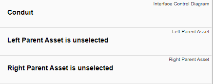
2. A drop-down will appear and a list of Assets will appear.
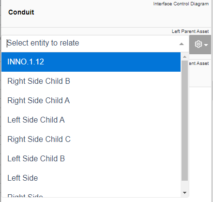
3. To filter Assets, type the name of the Asset to query the database.
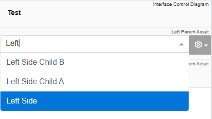
4. Select the desired Asset to have to appear on the ‘Interface Control Diagram.’

Notice the ‘Asset’ stays selected once it has been added. Since it is selected, the toolbar changes to include buttons for Parent ‘Asset’ which can be used on the construct. The sidebar also changes to include additional ‘Metadata,’ ‘Attributes,’ and ‘Relationships’ tabs.
5. Once you deselect the Parent ‘Asset’, all of the children that are decomposed by the Parent ‘Asset’ will automatically be brought into the diagram.

6. Click the ‘Save’ button located on the toolbar to persist your changes to your project’s database.

Note: The above steps gives a direct way to add an existing Parent Asset.Users may also use the New Parent Asset Button and with the Create Button that appears on the Modal, use the down arrow to recall an existing entity as displayed below:

Adding a Child Asset
A Child ‘Asset’ construct can be added to an ‘Interface Control Diagram’ via drag-and-drop. A Parent ‘Asset’ must be added to the diagram first before this construct can be added.
1. Within an ‘Interface Control Diagram’, click the ‘Asset’ icon in the ‘New’ tab of the left sidebar and continue to hold down the left mouse button.

2. Drag the ‘Asset’ icon over to the ‘Interface Control Diagram’ to either the left or right parent ‘Asset’.

3. When the Parent ‘Asset’ box highlights green, release the left mouse button to drop the new Child ‘Asset’ and add it to the diagram.

Notice the Child ‘Asset’ stays selected once it has been dropped. Since it is selected, the toolbar changes to include buttons for Child ‘Asset’, which can be used on the construct. The sidebar also changes to include additional ‘Metadata,’ ‘Attributes,’ and ‘Relationships’ tabs.
4. Once added to the diagram, enter a meaningful ‘Name’ for your new Child ‘Asset’ via the ‘Attributes’ tab of the left sidebar (focused automatically for convenience).

5. Click the ‘Save’ button located on the toolbar to persist your changes to your project’s database.
* Note: The above process describes using the ‘New’ tab of the left sidebar, which automatically generates a new entity to represent each new diagram construct. If you would like to reuse existing entities from your database to represent a new construct, use the ‘Existing’ tab instead.
Adding a Child Conduit
A Child ‘Conduit’ construct can be added to an ‘Interface Control Diagram’ via drag-and-drop.
1. Within an ‘Interface Control Diagram’, click the ‘Conduit’ icon in the ‘New’ tab of the left sidebar and continue to hold down the left mouse button.

2. Drag the ‘Conduit’ icon over to the ‘Interface Control Diagram’ to the parent ‘Conduit’, which is represented by a gray box.

3. When the Parent ‘Conduit’ box highlights green, release the left mouse button to drop the new Child ‘Conduit’ and add it to the diagram.

Notice the Child ‘Conduit’ stays selected once it has been dropped. Since it is selected, the toolbar changes to include buttons for Child ‘Conduit’, which can be used on the construct. The sidebar also changes to include additional ‘Metadata,’ ‘Attributes,’ and ‘Relationships’ tabs.
4. Once added to the diagram, enter a meaningful ‘Name’ for your new Child ‘Conduit’ via the ‘Attributes’ tab of the left sidebar (focused automatically for convenience).

5. Click the ‘Save’ button located on the toolbar to persist your changes to your project’s database.
* Note: The above process describes using the ‘New’ tab of the left sidebar, which automatically generates a new entity to represent each new diagram construct. If you would like to reuse existing entities from your database to represent a new construct, use the ‘Existing’ tab instead.
Adding an Input/Output
An ‘Input/Output’ construct can be added to an ‘Interface Control Diagram’ via drag-and-drop. A Child ‘Asset’ must be added to the diagram first before this construct can be added.
1. Within an ‘Interface Control Diagram’, click the ‘Input/Output’ icon in the ‘New’ tab of the left sidebar and continue to hold down the left mouse button.

2. Drag the ‘Input/Output’ icon over to the ‘Interface Control Diagram’ to a Child ‘Asset’.

3. When the Child ‘Asset’ box highlights green, release the left mouse button to drop the new ‘Input/Output’ and add it to the diagram.

Notice the ‘Input/Output’ stays selected once it has been dropped. Since it is selected, the toolbar changes to include buttons for ‘Input/Output’ which can be used on the construct. The sidebar also changes to include additional ‘Metadata,’ ‘Attributes,’ and ‘Relationships’ tabs.
4. Once added to the diagram, enter a meaningful ‘Name’ for your new ‘Input/Output’ via the ‘Attributes’ tab of the left sidebar (focused automatically for convenience).

5. Click the ‘Save’ button located on the toolbar to persist your changes to your project’s database.

* Note: The above process describes using the ‘New’ tab of the left sidebar, which automatically generates a new entity to represent each new diagram construct. If you would like to reuse existing entities from your database to represent a new construct, use the ‘Existing’ tab instead.
Removing a Construct
A construct can be easily removed from an ‘Interface Control Diagram.’
- Within an ‘Interface Control Diagram,’ select the construct you wish to remove. This will make the toolbar appear with applicable functions which can be used on the selected construct.

- Click the ‘Remove’ button to remove the construct from the diagram (as the default action).

* Note: The ‘Remove’ button also includes a drop-down menu where you can select ‘Delete from Database’ or the default option of ‘Remove from Diagram.’
Tutorial Video
To continue learning about General Diagrams, Click Here.
(Next Article: Interface Control Diagram Modifications & Settings)