
Using Class Diagrams
| Function | Description |
|---|---|
| Creating Class Diagrams | Using ‘Diagrams View’ in Innoslate, you can create a new ‘Class Diagram.’ |
| Class Diagram Constructs | The ‘Class Diagram’ supports six unique diagram constructs: a ‘Class,’ an ‘Operation,’ an ‘Attribute,’ an ‘Input Parameter,’ a ‘Return Type,’ and a ‘Logical Connection.’ |
| Adding a Class | A ‘Class’ construct can be added to a ‘Class Diagram’ via drag-and-drop. |
| Adding an Operation | An ‘Operation’ construct can be added to a ‘Class Diagram’ via drag-and-drop. |
| Adding an Attribute | An ‘Attribute’ construct can be added to a ‘Class Diagram’ via drag-and-drop. |
| Adding an Input Parameter | An ‘Input Parameter’ construct can be added to a ‘Class Diagram’ via drag-and-drop. |
| Adding a Return Type | A ‘Return Type’ construct can be added to a ‘Class Diagram’ via drag-and-drop. |
| Adding a Logical Connection | A ‘Logical Connection’ construct can be added to a ‘Class Diagram’ via drag-and-drop. |
| Removing a Construct | A construct can be easily removed from a ‘Class Diagram.’ |
| Assigning a Parent Class | A parent class can be assigned in a ‘Class Diagram’ via drag-and-drop. |
| Importing Java classes | Import Java classes into the ‘Class Diagram’. |
A ‘Class Diagram’ in the Unified Modeling Language (UML) is a type of static structure diagram that describes the structure of a system by showing the system’s classes, attributes, operations (or methods), and the relationships among objects.

Creating Class Diagrams
Within the ‘Diagrams Dashboard,’ users can create a new diagram by clicking the ‘ Create Diagram’ button in the top right corner of the page.
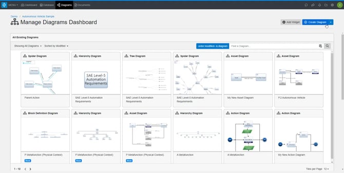
Clicking the ‘ Create Diagram’ button will open the Create Diagram dialog where you will be directed through the process of creating a new diagram.
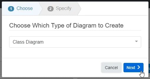
Create a Class Diagram
- Choose Which Type of Diagram to Create
In step 1, select ‘Class Diagram,’ under ‘General,’ as your diagram type.
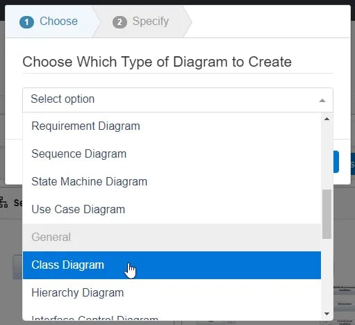
Click the ‘Next’ button.
- Specify New Root Action Information
In step 2, you will be prompted to input a diagram ‘Name,’ ‘Number’ (optional), and ‘Description’ (optional). Then, click the ‘Next’ button to save and automatically open your new Class Diagram.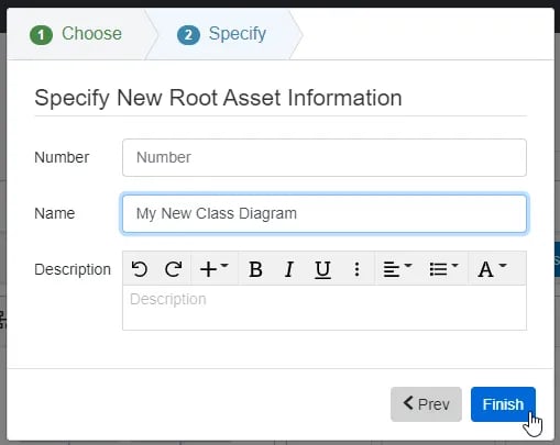
Class Diagram Constructs
The ‘Class Diagram’ supports six unique diagram constructs: a ‘Class,’ an ‘Operation,’ an ‘Attribute,’ an ‘Input Parameter,’ a ‘Return Type,’ and a ‘Logical Connection.’ Each diagram construct is described in more detail below:
-
Class
In the system model, an Asset entity is used to represent a ‘Class’ construct. A ‘Class’ must be added to the diagram first before any of the other constructs can be added. In the diagram, this construct is represented as a rounded box that contains the name of the ‘Class.’

-
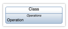
Operation
In the system model, an Action entity is used to represent an ‘Operation’ construct. A ‘Class’ must be added to the diagram first before this construct can be added. In the diagram, this construct is represented as a line of text containing the name of the ‘Operation’ in an “Operations” section of the ‘Class.’
-
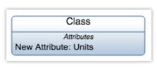
Attribute
In the system model, a Characteristic entity is used to represent an ‘Attribute’ construct. A ‘Class’ must be added to the diagram first before this construct can be added. In the diagram, this construct is represented as a line of text containing the name of the ‘Attribute,’ a semicolon, and the units of the ‘Attribute’ in an “Attributes” section of the ‘Class.’
-
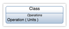
Input Parameter
In the system model, an Input/Output entity is used to represent a ‘Input Parameter’ construct. An ‘Operation’ must first be added to a ‘Class’ in the diagram before this construct can be added. In the diagram, this construct is represented as a line of text containing the units of the ‘Input Parameter’ in parenthesis.
-
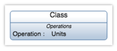
Return Type
In the system model, an Input/Output entity is used to represent a ‘Return Type’ construct. An ‘Operation’ must first be added to a ‘Class’ in the diagram before this construct can be added. In the diagram, this construct is represented as a semicolon and a line of text containing the units of the ‘Return Type.’
-
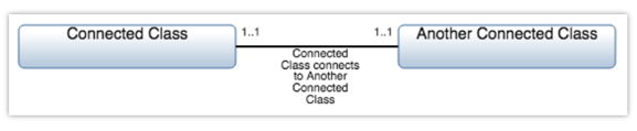
Logical Connection
In the system model, a Logical entity is used to represent a ‘Logical Connection’ construct. At least two ‘Class’ constructs must be added to the diagram first before a ‘Logical Connection’ can be added. In the diagram, this construct is represented as a solid line connecting two ‘Class’ constructs and a line label containing the name of the ‘Logical Connection.’
Adding a Class
A ‘Class’ construct can be added to a ‘Class Diagram‘ via drag-and-drop. A ‘Class’ must be added to the diagram first before any of the other constructs can be added.
- Within a ‘Class Diagram,’ click the ‘Class (Asset)’ icon in the ‘New’ tab of the left sidebar and continue to hold down the left mouse button.

- Drag the ‘Class (Asset)’ icon over to the adjacent diagram canvas.

- Release the left mouse button while over the diagram canvas to drop the new ‘Class’ and add it to the diagram.

Notice the ‘Class’ stays selected once it has been dropped. Since it is selected, the toolbar changes to include buttons for functions that can be used on the construct. The sidebar also changes to include additional ‘Metadata,’ ‘Attributes,’ and ‘Relationships’ tabs.
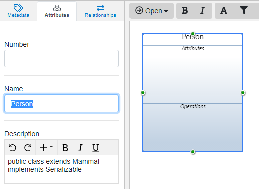
- Once added to the diagram, enter a meaningful ‘Name’ for your new ‘Class’ via the ‘Attributes’ tab of the left sidebar (focused automatically for convenience).

- Click the ‘Save’ button located on the toolbar to persist your changes to your project’s database.

* Note: The above process describes using the ‘New’ tab of the left sidebar, which automatically generates a new entity to represent each new diagram construct. If you would like to reuse existing entities from your database to represent a new construct, use the ‘Existing’ tab instead.
Adding an Operation
An ‘Operation’ construct can be added to a ‘Class Diagram‘ via drag-and-drop. A ‘Class‘ must be added to the diagram first before this construct can be added.
- Within a ‘Class Diagram,’ click the ‘Operation (Action)’ icon in the ‘New’ tab of the left sidebar and continue to hold down the left mouse button.

- Drag the ‘Operation (Action)’ icon over to the bottom section of the destination ‘Class’ of your choice.

- When the ‘Class’ box highlights green, release the left mouse button to drop the new ‘Operation’ and add it to the diagram.

Notice the ‘Operation’ stays selected once it has been dropped. Since it is selected, the toolbar changes to include buttons for functions that can be used on the construct. The sidebar also changes to include additional ‘Metadata,’ ‘Attributes,’ and ‘Relationships’ tabs.
- Once added to the diagram, enter a meaningful ‘Name’ for your new ‘Operation’ via the ‘Attributes’ tab of the left sidebar (focused automatically for convenience).

- Click the ‘Save’ button located on the toolbar to persist your changes to your project’s database.

* Note: The above process describes using the ‘New’ tab of the left sidebar, which automatically generates a new entity to represent each new diagram construct. If you would like to reuse existing entities from your database to represent a new construct, use the ‘Existing’ tab instead.
Adding an Attribute
An ‘Attribute’ construct can be added to a ‘Class Diagram‘ via drag-and-drop. A ‘Class‘ must be added to the diagram first before this construct can be added.
- Within a ‘Class Diagram,’ click the ‘Attribute (Characteristic)’ icon in the ‘New’ tab of the left sidebar and continue to hold down the left mouse button.

- Drag the ‘Attribute (Characteristic)’ icon over to the middle section of the destination ‘Class’ of your choice.

- When the ‘Class’ box highlights green, release the left mouse button to drop the new ‘Attribute’ and add it to the diagram.

Notice the ‘Attribute’ stays selected once it has been dropped. Since it is selected, the toolbar changes to include buttons for functions that can be used on the construct. The sidebar also changes to include additional ‘Metadata,’ ‘Attributes,’ and ‘Relationships’ tabs.
- Once added to the diagram, enter a meaningful ‘Name’ for your new ‘Attribute’ via the ‘Attributes’ tab of the left sidebar (focused automatically for convenience).

- Click the ‘Save’ button located on the toolbar to persist your changes to your project’s database.

* Note: The above process describes using the ‘New’ tab of the left sidebar, which automatically generates a new entity to represent each new diagram construct. If you would like to reuse existing entities from your database to represent a new construct, use the ‘Existing’ tab instead.
Adding an Input Parameter
An ‘Input Parameter’ construct can be added to a ‘Class Diagram‘ via drag-and-drop. An ‘Operation‘ must first be added to a ‘Class‘ in the diagram before this construct can be added.
- Within a ‘Class Diagram,’ click the ‘Input Parameter (Input/Output)’ icon in the ‘New’ tab of the left sidebar and continue to hold down the left mouse button.

- Drag the ‘Input Parameter (Input/Output)’ icon over to the bottom section of the ‘Class’ of the destination ‘Operation’ of your choice.

- When the ‘Operation’ box highlights green, release the left mouse button to drop the new ‘Input Parameter’ and add it to the diagram.

Notice the ‘Input Parameter’ stays selected once it has been dropped. Since it is selected, the toolbar changes to include buttons for functions that can be used on the construct. The sidebar also changes to include additional ‘Metadata,’ ‘Attributes,’ and ‘Relationships’ tabs.
- Once added to the diagram, you can specify the unit(s) for your ‘Input Parameter’ under the ‘Attributes’ tab of the left sidebar.

- Click the ‘Save’ button located on the toolbar to persist your changes to your project’s database.

* Note: The above process describes using the ‘New’ tab of the left sidebar, which automatically generates a new entity to represent each new diagram construct. If you would like to reuse existing entities from your database to represent a new construct, use the ‘Existing’ tab instead.
Adding a Return Type
A ‘Return Type’ construct can be added to a ‘Class Diagram‘ via drag-and-drop. An ‘Operation‘ must first be added to a ‘Class‘ in the diagram before this construct can be added.
- Within a ‘Class Diagram,’ click the ‘Return Type (Input/Output)’ icon in the ‘New’ tab of the left sidebar and continue to hold down the left mouse button.

- Drag the ‘Return Type (Input/Output)’ icon over to the bottom section of the ‘Class’ of the destination ‘Operation’ of your choice.

- When the ‘Operation’ box highlights green, release the left mouse button to drop the new ‘Return Type’ and add it to the diagram.

Notice the ‘Return Type’ stays selected once it has been dropped. Since it is selected, the toolbar changes to include buttons for functions that can be used on the construct. The sidebar also changes to include additional ‘Metadata,’ ‘Attributes,’ and ‘Relationships’ tabs.
- Once added to the diagram, you can specify the unit(s) for your ‘Return Type’ under the ‘Attributes’ tab of the left sidebar.

- Click the ‘Save’ button located on the toolbar to persist your changes to your project’s database.

* Note: The above process describes using the ‘New’ tab of the left sidebar, which automatically generates a new entity to represent each new diagram construct. If you would like to reuse existing entities from your database to represent a new construct, use the ‘Existing’ tab instead.
Adding a Logical Connection
A ‘Logical Connection’ can be added to the ‘Class Diagram‘ via drag-and-drop. The example used on this page connects two ‘Class‘ constructs with a ‘Logical Connection.’
- Within a ‘Class Diagram,’ select the ‘Class’ you would like connected to another ‘Class.’

- Click the green circle and continue to hold down the left mouse button.

- Drag the green circle over to another ‘Class’ of your choice.

- When the parent ‘Class’ box highlights green, release the left mouse button over the ‘Simple Association (connected by)’ section to drop the new ‘Logical Connection’ and add it to the diagram.

Notice the ‘Logical Connection’ stays selected once it has been dropped. Since it is selected, the toolbar changes to include buttons for functions that can be used on the construct. The sidebar also changes to include additional ‘Metadata,’ ‘Attributes,’ and ‘Relationships’ tabs.
- Once added to the diagram, enter a meaningful ‘Name’ for your new ‘Logical Connection’ via the ‘Attributes’ tab of the left sidebar (focused automatically for convenience).

- If wanting to change the logical connection type, select the ‘Paths’ button. You can select ‘Aggregation (related to),’ ‘Composition (decomposed by),’ ‘Generalization (extend),’ or ‘Simple Association (connected by).’

- Click the ‘Save’ button located on the toolbar to persist your changes to your project’s database.

* Note: The above process describes using the ‘New’ tab of the left sidebar, which automatically generates a new entity to represent each new diagram construct. If you would like to reuse existing entities from your database to represent a new construct, use the ‘Existing’ tab instead.
Removing a Construct
A construct can be easily removed from a ‘Class Diagram.’
- Within a ‘Class Diagram,’ select the construct you wish to remove. This will make the toolbar appear with applicable functions which can be used on the selected construct.

- Click the ‘Remove’ button to remove the construct from the diagram (as the default action).

* Note: The ‘Remove’ button also includes a drop-down menu where you can select ‘Delete from Database’ or the default option of ‘Remove from Diagram.’
Assigning a Parent Class
The parent of a ‘Class’ construct can be assigned in the ‘Class Diagram‘ via drag-and-drop. Both the “to-be” parent and child ‘Class’ constructs must be added to the diagram first before the parent can be assigned.
- Within a ‘Class Diagram,’ select the ‘Class’ you would like to assign as the parent.

- Click the green circle and continue to hold down the left mouse button.

- Drag the green circle over to the child ‘Class’ of your choice.

- When the child ‘Class’ box highlights green, release the left mouse button over the ‘Composition’ section to add a decomposed by relationship.

- Once added to the diagram, the new relationship should appear as a filled diamond shape and directional arrow from the parent to the child ‘Class’ construct.

- Click the ‘Save’ button located on the toolbar to persist your changes to your project’s database.

Importing Java Classes
The Class diagram can import java classes and convert them into class diagrams.
Importing a Java Class
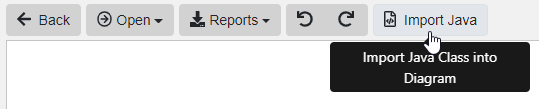
Java code can be added to a ‘Class Diagram’ via the ‘Import Java’ button on the toolbar.
- Within a ‘Class Diagram’, click the ‘Import Java’ button on the toolbar.
- There are 2 import options for your Java class: text and file upload.
To upload text, simply paste your Java class code into the text box.
To upload a file, drag and drop your .java file over the drop area, or click within the drop area to browse your computer’s file system to select the file to upload.
- Verify that your Java file contains a package statement and the code uses valid Java 8 syntax. Once you have uploaded your file, click ‘Apply’ to parse the Java file into the ‘Class Diagram.’
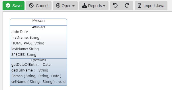
- Assets (Java class), Attributes (Java class variables) and Operations (Java methods) are each parsed into the different Innoslate entities on the ‘Class Diagram’. For Attributes and Operations, the modifiers and annotations are added to the entity’s description. The Java type (i.e. int, String, etc.) is added to the entity’s ‘Units’ attribute. If the class variable was given an initial value in the declaration, that value is added to the entity’s ‘Value’ attribute.

The Java importer supports all of the basic Java 8 class structures, including Concrete, Enum, Static, Final, Abstract, and Interface.
The importer also supports nested classes which will be parsed into separate Assets and will draw the decomposition relationship between the 2 Assets if the outer Java class extends or implements the inner class.
To continue learning about General Diagrams, Click Here.
(Next Article: Class Diagram Modifications & Settings)