
Using Use Case Diagrams
| Function | Description |
|---|---|
| Creating Use Case Diagrams | Using ‘Diagrams View’ in Innoslate, you can create a new ‘Use Case Diagram’. |
| Use Case Diagram Constructs | The ‘Use Case Diagram’ supports two unique diagram constructs: a ‘Use Case’ and a ‘Performer.’ |
| Adding a Use Case | A ‘Use Case’ construct can be added to a ‘Use Case Diagram’ via drag-and-drop. |
| Adding a Performer | A ‘Performer’ construct can be added to a ‘Use Case Diagram’ via drag-and-drop. |
| Adding a System Boundary | A 'System Boundary' construct can be added to a 'Use Case Diagram.' |
| Assigning a Performer | The ‘Performer’ of a ‘Use Case’ construct can be assigned in the ‘Use Case Diagram’ via drag-and-drop. |
| Removing a Construct | A construct can be easily removed from a ‘Use Case Diagram.’ |
The ‘Use Case Diagram’ is a behavior diagram that shows how an Actor interacts with a system under different Use Cases and their relationships.

Creating Use Case Diagrams
Within the ‘Diagrams Dashboard,’ users can create a new diagram by clicking the ‘ Create Diagram’ button in the top right corner of the page.

Clicking the ‘Create Diagram’ button will open the Create Diagram dialog where you will be directed through the process of creating a new diagram.
Create a Use Case Diagram
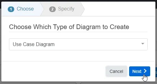
- Choose Which Type of Diagram to Create
In step 1, select ‘Use Case Diagram,’ under ‘SysML,’ as your diagram type.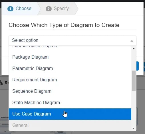
Click the ‘Next’ button.
- Specify New Root Action Information
In step 2, you will be prompted to input a diagram ‘Name,’ ‘Number’ (optional), and ‘Description’ (optional). Then, click the ‘Finish’ button to save and automatically open your new Use Case Diagram.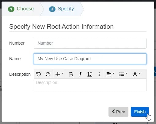
Use Case Diagram Constructs
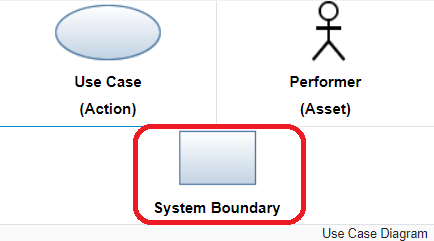
The ‘Use Case Diagram’ supports three unique diagram constructs: a ‘Use Case (Action)’, a ‘Performer (Asset)’ and a 'System Boundary.' Each diagram construct is described in more detail below:
-
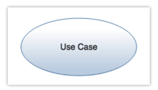
Use Case (Action)
In the system model, an Action entity is used to represent a ‘Use Case’ construct. In the diagram, this construct is represented as an oval and contains the name of the ‘Use Case.’
-
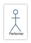
Performer (Asset)
In the system model, an Asset entity is used to represent a ‘Performer’ construct. In the diagram, this construct is represented as a stick figure with the name of the ‘Performer’ underneath.
-
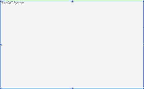
System Boundary
A System Boundary is a rectangular visual representation utilized in a Use Case Diagram to distinguish between the Use Cases and Performers that occur internally and externally, within and outside of the System Boundary.
Adding a Use Case
A ‘Use Case’ construct can be added to a ‘Use Case Diagram‘ via drag-and-drop.
- Within a ‘Use Case Diagram,’ click the ‘Use Case’ icon in the ‘New’ tab of the left sidebar and continue to hold down the left mouse button.

- Drag the ‘Use Case’ icon over to the adjacent diagram canvas

or 'System Boundary'.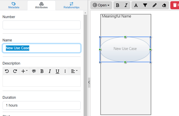
- Release the left mouse button while over the diagram canvas to drop the new ‘Use Case’ and add it to the diagram.

Notice the ‘Use Case’ stays selected once it has been dropped. Since it is selected, the toolbar changes to include buttons for functions that can be used on the construct. The sidebar also changes to include additional ‘Metadata,’ ‘Attributes,’ and ‘Relationships’ tabs.
- Once added to the diagram, enter a meaningful ‘Name’ for your new ‘Use Case’ via the ‘Attributes’ tab of the left sidebar (focused automatically for convenience).

- Click the ‘Save’ button located on the toolbar to persist your changes to your project’s database.

* Note: The above process describes using the ‘New’ tab of the left sidebar, which automatically generates a new entity to represent each new diagram construct. If you would like to reuse existing entities from your database to represent a new construct, use the ‘Existing’ tab instead.
Adding a Performer
A ‘Performer’ construct can be added to a ‘Use Case Diagram‘ via drag-and-drop.
- Within a ‘Use Case Diagram,’ click the ‘Performer’ icon in the ‘New’ tab of the left sidebar and continue to hold down the left mouse button.

- Drag the ‘Performer’ icon to the canvas.

- Release the left mouse button while over the diagram canvas to drop the new ‘Performer’ and add it to the diagram.

Notice the ‘Performer’ icon stays selected once it has been dropped. Since it is selected, the toolbar changes to include buttons for functions that can be used on the construct. The sidebar also changes to include additional ‘Metadata,’ ‘Attributes,’ and ‘Relationships’ tabs.
- Once added to the diagram, enter a meaningful ‘Name’ for your new ‘Performer’ via the ‘Attributes’ tab of the left sidebar (focused automatically for convenience).

- Click the ‘Save’ button located on the toolbar to persist your changes to your project’s database.

* Note: The above process describes using the ‘New’ tab of the left sidebar, which automatically generates a new entity to represent each new diagram construct. If you would like to reuse existing entities from your database to represent a new construct, use the ‘Existing’ tab instead.
Adding a System Boundary
A ‘System Boundary’ construct can be added to a ‘Use Case Diagram‘ via drag-and-drop.
- Within a ‘Use Case Diagram,’ click the ‘System Boundary’ icon in the ‘New’ tab of the left sidebar and continue to hold down the left mouse button.
- Drag the ‘System Boundary’ construct to the canvas.
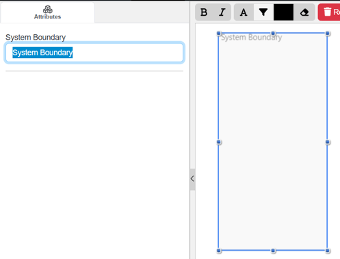
- Release the left mouse button while over the diagram canvas to drop the new ‘System Boundary’ and add it to the diagram.
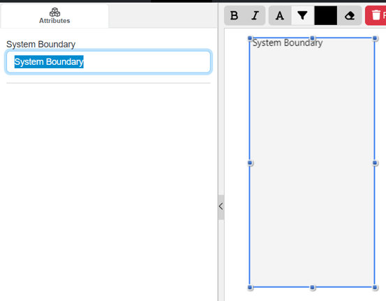
Notice the ‘System Boundary’ icon stays selected once it has been dropped. Since it is selected, the toolbar changes to include buttons for functions that can be used on the construct. The sidebar also changes to include a name field to name the System Boundary.
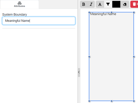
-
Once added to the diagram, enter a meaningful ‘Name’ for your new ‘System Boundary’ via the ‘Name’ field on the left sidebar (focused automatically for convenience).
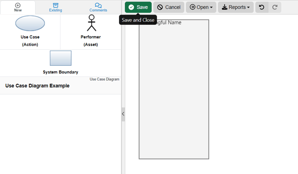
- Click the ‘Save’ button located on the toolbar to persist your changes to your project’s database.
Assigning a Performer
The ‘Performer’ of a ‘Use Case’ construct can be assigned in the ‘Use Case Diagram‘ via drag-and-drop. Both the “to-be” performed ‘Use Case’ and the ‘Performer’ constructs must be added to the diagram first before the performer can be assigned.
- Within the ‘Use Case Diagram,’ select the ‘Performer’ which you would like to assign to a ‘Use Case.’

- Click the green circle and continue to hold down the left mouse button.

- Drag the green circle over to the ‘Use Case’ of your choice.

- When the parent ‘Use Case’ oval highlights green, release the left mouse button to add a performs/performed by relationship.

- Once added to the diagram, the new relationship should appear as an arrow between the ‘Performer’ and ‘Use Case’ constructs.

- Click the ‘Save’ button located on the toolbar to persist your changes to your project’s database.

* Note: The above process describes using the ‘New’ tab of the left sidebar, which automatically generates a new entity to represent each new diagram construct. If you would like to reuse existing entities from your database to represent a new construct, use the ‘Existing’ tab instead.
Removing a Construct
A construct can be easily removed from a ‘Use Case Diagram.’
- Within a ‘Use Case Diagram,’ select the construct you wish to remove. This will make the toolbar appear with applicable functions which can be used on the selected construct.

- Click the ‘Remove’ button to remove the construct from the diagram (as the default action).

* Note: The ‘Remove’ button also includes a drop-down menu where you can select ‘Delete from Database’ or the default option of ‘Remove from Diagram.
To continue learning about SysML Diagrams, Click Here.
(Next Article: Use Case Diagram Modifications & Settings)