
Using State Machine Diagrams
| Function | Description |
|---|---|
| Creating State Machine Diagrams | Using ‘Diagrams View’ in Innoslate, you can create a new ‘State Machine Diagram’. |
| State Machine Diagram Constructs | The ‘State Machine Diagram’ supports ten unique diagram constructs and 2 subconstructs: a ‘State,’ an ‘Initial State,’ a ‘Final State,’ a 'History State,' a 'Parallel State,' a 'Region State,' an 'Entry Action,' a 'Do Action,' an 'Exit Action,' a ‘Transition,’ and 2 subconstructs a 'Transition Guard' and 'Transition Effect.' |
| Adding a State | ‘State’ (or 'Parallel' or 'Region' State) constructs can be added to a ‘State Machine Diagram’ via drag-and-drop. |
| Adding a Region State | A Region State can be added to a 'Parallel State.' |
| Adding an Initial State | An ‘Initial State’ construct can be added to a ‘State Machine Diagram’ via drag-and-drop. |
| Adding a Final State | A ‘Final State’ construct can be added to a ‘State Machine Diagram’ via drag-and-drop. |
| Adding a History State | A ‘History State’ construct can be added to a ‘State Machine Diagram’ via drag-and-drop. |
| Adding an Action | An ‘Action’ ('Entry,' 'Do' or 'Exit') construct can be added to a ‘State Machine Diagram’ via drag-and-drop. |
| Adding a Transition and its subconstructs | A walkthrough on adding a 'Transition' and it's subconstructs, 'Transition Guard' and 'Transition Effect.' |
| Removing a Construct | A construct can be easily removed from a ‘State Machine Diagram.’ |
The ‘State Machine Diagram’ is a behavior diagram showing states and their transitions.

Creating State Machine Diagrams
Within the ‘Diagrams Dashboard,’ users can create a new diagram by clicking the ‘ Create Diagram’ button in the top right corner of the page.

Clicking the ‘ Create Diagram’ button will open the Create Diagram window where you will be directed through the process of creating a new diagram.
Create a State Machine Diagram
- Choose Which Type of Diagram to Create
In step 1, select ‘State Machine Diagram,’ under ‘SysML,’ as your diagram type.
Click the ‘Next’ button.

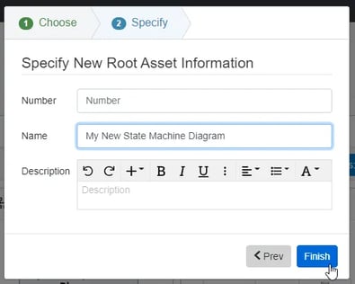
- Specify New Root Action Information
In step 2, you will be prompted to input a diagram ‘Name,’ ‘Number’ (optional), and ‘Description’ (optional). Then, click the ‘Finish’ button to save and automatically open your new State Machine Diagram.
State Machine Diagram Constructs
The ‘State Machine Diagram’ supports four unique diagram constructs: a ‘State,’ an ‘Initial State,’ a ‘Final State,’ and a ‘Transition,’ Each diagram construct is described in more detail below:
-
State
This construct is used to capture significant conditions experienced during the life of a system. In the system model, a Characteristic entity with a State label is generated to represent a ‘State’ construct. In the diagram, this construct is represented as a rounded block containing the name of the ‘State.’

-
Initial State
This construct is used to specify the original state of a system at the beginning of a system’s life. In the system model, a Characteristic entity with both an Initial State label and a State label is applied to represent an ‘Initial State’ construct. In the diagram, this construct is represented as a filled circle.

-
History State
A History State is used to remember the previous state of a system when it is interrupted and needs to continue. In the system model, a Characteristic entity with both a History State label and a State label is applied to represent a ‘History State’ construct. In the diagram, this construct is represented as a filled circle with a 'H' in it.

-
Parallel/Region State
This construct is used to specify the parallel/ongoing state of the system when occurring. In the system model, a Characteristic entity is generated with both a Parallel State label and a State label applied to represent a ‘Parallel State’ construct. The two states create a node action that creates an environment for other states/actions can occur.

-
Final State
This construct is used to specify the final state of a system at the end of a system’s life. In the system model, a Characteristic entity is generated with both a Final State label and a State label applied to represent a ‘Final State’ construct. In the diagram, this construct is represented as a circle with a dot inside.

-
Entry/Do/Exit (Action)
The Entry, Do, and Exit actions are used to specify the action occurring on a State Block. Only one of each action type (Entry, Do, Exit) may be shown. Also, they can only be added to a Parallel State Block or State Block on the State Machine Diagram canvas.
-
Transition
This construct is used to capture events that occur during the life of a system.
In the system model, an Action entity is generated to represent the ‘Transition’ construct with a pushed by/pushes relationship to the source state and a fetches/fetched by relationship to the target state. There are some scenarios in which are needed for "Transition Node":
-
At least two ‘State’ constructs or one ‘Initial State’ construct
-
AND one ‘State’ construct or one ‘State’ construct
-
AND one ‘Final State’ construct must be added to the diagram first before a ‘Transition’ can be added.
In the diagram, this construct is represented as an arrow (directed line) connecting two other diagram constructs and a line label containing the name of the ‘Transition.’

-
Transition Guard

The Transition Guard is a subcontract to a Transition Construct. It is a textual expression placed in brackets that is added next to the Name of the Transition construct as underlined in the image above.
-
Transition Effect

The Transition Effect is a subconstruct on a Transition construct and is an Action or behavior executed during the Transition. The Transition Effect is expressed after the foward slash placed after the name of the Transition construct.
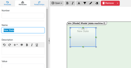
Adding a State (State or Parallel)
A ‘State’ construct can be added to a ‘State Machine Diagram‘ via drag-and-drop.
- Within a ‘State Machine Diagram,’ click the ‘State (Characteristic)’ or 'Parallel State (Characteristic)' icon in the ‘New’ tab of the left sidebar and continue to hold down the left mouse button.

- Drag the ‘State (Characteristic)’ or 'Parallel State (Characteristic)' icon over to the adjacent diagram canvas.
- Release the left mouse button while over the diagram canvas to drop the new ‘State’ and add it to the diagram.

Notice the ‘State’ stays selected once it has been dropped. Since it is selected, the toolbar changes to include buttons for functions that can be used on the construct. The sidebar also changes to include additional ‘Metadata,’ ‘Attributes,’ and ‘Relationships’ tabs.
Also notice, if using a 'Parallel State,' it automatically comes with 2 regions:
- Once added to the diagram, enter a meaningful ‘Name’ for your new ‘State’ via the ‘Attributes’ tab of the left sidebar (focused automatically for convenience).

- Click the ‘Save’ button located on the toolbar to persist your changes to your project’s database.

Adding a Region State
A Parallel State must already be added to the canvas before a new Region State can be added.
- Within a ‘State Machine Diagram,’ click the ‘Region State (Characteristic)’ icon in the ‘New’ tab of the left sidebar and continue to hold down the left mouse button.

- Drag the ‘Region State (Characteristic)’ icon over the Parallel State block on the canvas.

3. Release the left mouse button while over the diagram canvas to drop the new ‘Initial State’ and add it to the diagram.

Notice the ‘Region State’ stays selected once it has been dropped. Since it is selected, the toolbar changes to include buttons for functions that can be used on the construct. The sidebar also changes to include additional ‘Metadata,’ ‘Attributes,’ and ‘Relationships’ tabs.
4. Once added to the diagram, enter a meaningful ‘Name’ for your new ‘State’ via the ‘Attributes’ tab of the left sidebar (focused automatically for convenience).

5. Click the ‘Save’ button located on the toolbar to persist your changes to your project’s database.

Adding an Initial State
An ‘Initial State’ construct can be added to a ‘State Machine Diagram‘ via drag-and-drop.
- Within a ‘State Machine Diagram,’ click the ‘Initial (Characteristic)’ icon in the ‘New’ tab of the left sidebar and continue to hold down the left mouse button.

- Drag the ‘Initial (Characteristic)’ icon over to the adjacent diagram canvas.

- Release the left mouse button while over the diagram canvas to drop the new ‘Initial State’ and add it to the diagram.

Notice the ‘Initial State’ stays selected once it has been dropped. Since it is selected, the toolbar changes to include buttons for functions that can be used on the construct. The sidebar also changes to include additional ‘Metadata,’ ‘Attributes,’ and ‘Relationships’ tabs.
- Once added to the diagram, enter a meaningful ‘Name’ for your new ‘Initial State’ via the ‘Attributes’ tab of the left sidebar (focused automatically for convenience).

- Click the ‘Save’ button located on the toolbar to persist your changes to your project’s database.

Adding a Final State
A ‘Final State’ construct can be added to a ‘State Machine Diagram‘ via drag-and-drop.
- Within a ‘State Machine Diagram,’ click the ‘Final (Characteristic)’ icon in the ‘New’ tab of the left sidebar and continue to hold down the left mouse button.

- Drag the ‘Final (Characteristic)’ icon over to the adjacent diagram canvas.

- Release the left mouse button while over the diagram canvas to drop the new ‘Final State’ and add it to the diagram.

Notice the ‘Final State’ stays selected once it has been dropped. Since it is selected, the toolbar changes to include buttons for functions that can be used on the construct. The sidebar also changes to include additional ‘Metadata,’ ‘Attributes,’ and ‘Relationships’ tabs.
- Once added to the diagram, enter a meaningful ‘Name’ for your new ‘Final State’ via the ‘Attributes’ tab of the left sidebar (focused automatically for convenience).

- Click the ‘Save’ button located on the toolbar to persist your changes to your project’s database.

Adding a History State
A ‘History State’ construct can be added to a ‘State Machine Diagram‘ via drag-and-drop.
- Within a ‘State Machine Diagram,’ click the ‘History (Characteristic)’ icon in the ‘New’ tab of the left sidebar and continue to hold down the left mouse button.

- Drag the ‘History (Characteristic)’ icon over to the adjacent diagram canvas.

- Release the left mouse button while over the diagram canvas to drop the new ‘Final State’ and add it to the diagram.

Notice the ‘History State’ stays selected once it has been dropped. Since it is selected, the toolbar changes to include buttons for functions that can be used on the construct. The sidebar also changes to include additional ‘Metadata,’ ‘Attributes,’ and ‘Relationships’ tabs.
- Once added to the diagram, enter a meaningful ‘Name’ for your new ‘History State’ via the ‘Attributes’ tab of the left sidebar (focused automatically for convenience).

- Click the ‘Save’ button located on the toolbar to persist your changes to your project’s database.

Adding an Action
An Entry, Do, or Exit ‘Action’ construct can be added to a ‘State Machine Diagram‘ via drag-and-drop.
- A State construct (State or Parallel) must already be on the canvas before executing the next steps.
- Within a ‘State Machine Diagram,’ click the desired ‘Action’ icon in the ‘New’ tab of the left sidebar and continue to hold down the left mouse button.

3. Drag the ‘Action’ icon over to the adjacent diagram canvas.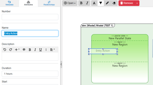
4. Release the left mouse button while over the diagram canvas to drop the new ‘Final State’ and add it to the diagram.
Notice the ‘Action’ stays selected once it has been dropped. Since it is selected, the toolbar changes to include buttons for functions that can be used on the construct. The sidebar also changes to include additional ‘Metadata,’ ‘Attributes,’ and ‘Relationships’ tabs.
5. Once added to the diagram, enter a meaningful ‘Name’ for your new ‘Action’ via the ‘Attributes’ tab of the left sidebar (focused automatically for convenience).

6. Click the ‘Save’ button located on the toolbar to persist your changes to your project’s database.

Adding a Transition
A ‘Transition’ construct can be added to a ‘State Machine Diagram‘ via drag-and-drop on the diagram canvas.
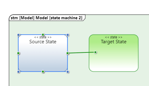
1. Within a ‘State Machine Diagram,’ select the ‘State’ you would like connected to another ‘State.’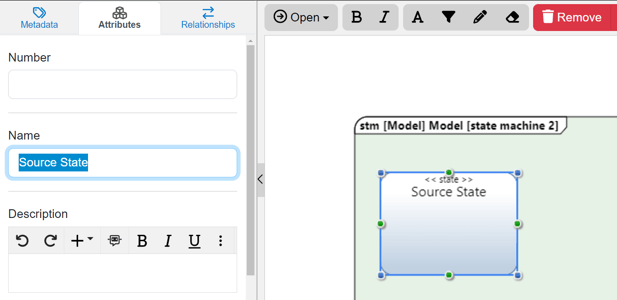
2. Click the green circle and continue to hold down the left mouse button.

3. Drag the green circle over to another ‘State’ of your choice.

4. When the target ‘State’ block highlights green, release the left mouse button to drop the new ‘Transition’ and add it to the diagram.
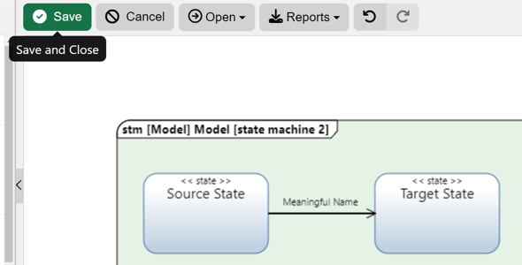
Notice the ‘Transition’ stays selected once it has been dropped. Since it is selected, the toolbar changes to include buttons for functions that can be used on the construct. The sidebar also changes to include additional ‘Metadata,’ ‘Attributes,’ and ‘Relationships’ tabs.
5. Once added to the diagram, enter a meaningful ‘Name’ for your new ‘Transition’ via the ‘Attributes’ tab of the left sidebar (focused automatically for convenience).

6. Click the ‘Save’ button located on the toolbar to persist your changes to your project’s database.
* Note: The above process describes using the ‘New’ tab of the left sidebar, which automatically generates a new entity to represent each new diagram construct. If you would like to reuse existing entities from your database to represent a new construct, use the ‘Existing’ tab instead.
Adding a Transition Guard
1. To add a Transition Guard, users must have already added a Transition.
2. Once this has been completed, users must go to the Attributes Tab on the left sidebar and go to the Guard Attribute to add their desired text.
3. Click outside of the construct so the ‘Save’ button appears on the top of the toolbar to persist your changes to your project’s database.

Adding a Transition Effect
1. To add a Transition Effect to a Transition Construct, users must first have created a Transition.
2. Then users must click on the 'Open' dropdown and select Entity View.

3. Users then must add a child Action to the Transition by adding the child Entity to the 'decomposed by' relationship under the relationships table on the right side of Entity View.

4. After the child Action has been added, be sure to 'Save' the relationship. This is a green button will appear on the top left.

5. Upon saving the change, Innoslate will take the user back to the diagram where they will see the added Transition Effect.

Removing a Construct
A construct can be easily removed from a ‘State Machine Diagram.’
Within a ‘State Machine Diagram,’ select the construct you wish to remove. This will make the toolbar appear with applicable functions which can be used on the selected construct.
Click the ‘Remove’ button to remove the construct from the diagram (as the default action).

* Note: The ‘Remove’ button also includes a drop-down menu where you can select ‘Delete from Database’ or the default option of ‘Remove from Diagram.’
Tutorial Video
To continue learning about SysML Diagrams, Click Here.
(Next Article: State Machine Diagram Modifications & Settings)