
Using Parametric Diagrams
| Function | Description |
|---|---|
| Creating Parametric Diagrams | Using the ‘Manage Diagrams Dashboard’ in Innoslate, you can create a new ‘Parametric Diagram’. |
| Parametric Diagram Constructs | The ‘Parametric Diagram’ supports five unique diagram constructs: a ‘Block (Asset),’ a ‘Parameter (Characteristic),’ a ‘Value (Characteristic), ‘Constraint (Equation),’ and a ‘Connector.’ |
| Adding a Constraint | A ‘Constraint’ can be added to a ‘Parametric Diagram’ via drag-and-drop. |
| Adding a Block | A ‘Block’ can be added to a ‘Parametric Diagram’ via drag-and-drop. |
| Adding a Value | A ‘Value’ can be added to a ‘Parametric Diagram’ via drag-and-drop. |
| Adding a Parameter | A ‘Parameter’ can be added to a ‘Parametric Diagram’ via drag-and-drop. |
| Adding a Connector | A ‘Connector’ can be added to a ‘Parametric Diagram’ via drag-and-drop. |
| Removing a Construct | A construct can be easily removed from a ‘Parametric Diagram.’ |
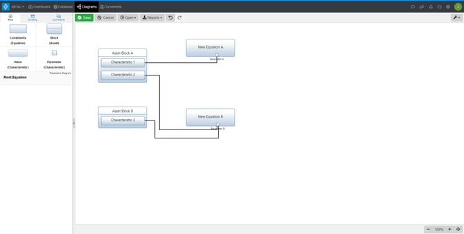
The ‘Parametric Diagram’ is a structure diagram showing mathematical relationships, performance constraints, and parameters among the pieces of the system being designed.
Creating Parametric Diagrams
Within the ‘Diagrams Dashboard,’ users can create a new diagram by clicking the ‘+ Create Diagram’ button on the right of the page.

Clicking the ‘+ Create Diagram’ button will open the Create Diagram dialog where you will be directed through the process of creating a new diagram.
Create a Parametric Diagram
1. Choose Which Type of Diagram to Create
In step one, select ‘Parametric Diagram,’ under ‘SysML,’ as your diagram type.

2. Click the ‘Next’ button.

3. Specify New Root Equation Information
In step three, you will be prompted to input a diagram ‘Name,’ ‘Number’ (optional), and ‘Description’ (optional). Then, click the ‘Finish’ button to save and automatically open your new Parametric Diagram.

Parametric Diagram Constructs
The ‘Parametric Diagram‘ supports four unique diagram constructs: a ‘Constraint,’ a ‘Block,’ a ‘Value,’ a ‘Parameter,’ and a ‘Connector.’ Each diagram construct is described in more detail below:
-
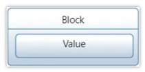
Block
A Block Property represents a part or aspect of a system element, defined according to the structure described in a Block definition. In Parametric Diagrams, a Block Property typically serves as the context or container for Value Properties, Constraint Properties, and other internal structure. A Block Property helps encapsulate and organize the elements needed for constraint analysis.
-
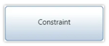
Constraint
A Constraint Block defines mathematical or logical expressions that represent constraints within a system. These blocks encapsulate equations or rules, such as F = m * a, and specify parameters < = > that can be bound to system properties. By abstracting constraints into blocks, they can be applied consistently across different parts of the model.
-
Value
Value Properties represent quantifiable attributes of system elements, such as length, mass, or temperature. These properties can be bound to Constraint Parameters to participate in constraint evaluations, enabling the analysis of system behavior based on specific values.
-
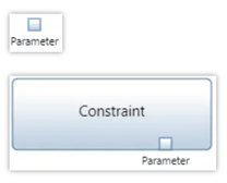
Parameter
Constraint Parameters are variables defined within a Constraint Block that represent the inputs and outputs of the constraint equation or rule. These parameters are the points of interaction between the constraint and the system’s properties, allowing for the binding of specific values during analysis.
-
Connector
A Binding Connector establishes an equality relationship between two properties, ensuring they share the same value. In Parametric Diagrams, Binding Connectors link Constraint Parameters to system properties, facilitating the flow of values into and out of constraints.
Adding a Constraint
A ‘Constraint’ construct can be added to a ‘Parametric Diagram‘ via drag-and-drop.
- Within a ‘Parametric Diagram,’ click the ‘Constraints (Equation)’ icon in the ‘New’ tab of the left sidebar and continue to hold down the left mouse button.

- Drag the ‘Constraints (Equation)‘ icon over to the adjacent diagram canvas.

- Release the left mouse button while over the diagram canvas to drop the new ‘Constraint’ and add it to the diagram.

Notice the ‘Constraint‘ stays selected once it has been dropped. Since it is selected, the toolbar changes to include buttons for functions that can be used on the construct. The sidebar also changes to include additional ‘Metadata,’ ‘Attributes,’ and ‘Relationships’ tabs.
- Once added to the diagram, enter a meaningful ‘Name’ for your new ‘Constraint‘ via the ‘Attributes’ tab of the left sidebar (focused automatically for convenience).

- Click the ‘Save’ button located on the toolbar to persist your changes to your project’s database.

* Note: The above process describes using the ‘New’ tab of the left sidebar, which automatically generates a new entity to represent each new diagram construct. If you would like to reuse existing entities from your database to represent a new construct, use the ‘Existing’ tab instead.
Adding a Block
A ‘Block’ construct can be added to a ‘Parametric Diagram‘ via drag-and-drop. A ‘Block’ must be added to the diagram before a ‘Value’ construct can be added.
- Within a ‘Parametric Diagram,’ click the ‘Block (Asset)’ icon in the ‘New’ tab of the left sidebar and continue to hold down the left mouse button.

- Drag the ‘Block (Asset)‘ icon over to the adjacent diagram canvas.

- Release the left mouse button while over the diagram canvas to drop the new ‘Block’ and add it to the diagram.

Notice the ‘Block’ stays selected once it has been dropped. Since it is selected, the toolbar changes to include buttons for functions that can be used on the construct. The sidebar also changes to include additional ‘Metadata,’ ‘Attributes,’ and ‘Relationships’ tabs.
- Once added to the diagram, enter a meaningful ‘Name’ for your new ‘Block’ via the ‘Attributes’ tab of the left sidebar (focused automatically for convenience).

- Click the ‘Save’ button located on the toolbar to persist your changes to your project’s database.

* Note: The above process describes using the ‘New’ tab of the left sidebar, which automatically generates a new entity to represent each new diagram construct. If you would like to reuse existing entities from your database to represent a new construct, use the ‘Existing’ tab instead.
Adding a Value
A ‘Value’ construct can be added to a ‘Parametric Diagram‘ via drag-and-drop. A ‘Block’ must be added to the diagram first before this construct can be added.
- Within a ‘Parametric Diagram,’ click the ‘value (Characteristic)’ icon in the ‘New’ tab of the left sidebar and continue to hold down the left mouse button.

- Drag the ‘Value (Characteristic)‘ icon over to the adjacent diagram canvas.

- When the ‘Block’ box highlights green, release the left mouse button to drop the new ‘Value’ and add it to the diagram.

Notice the ‘Value‘ stays selected once it has been dropped. Since it is selected, the toolbar changes to include buttons for functions that can be used on the construct. The sidebar also changes to include additional ‘Metadata,’ ‘Attributes,’ and ‘Relationships’ tabs.
- Once added to the diagram, enter a meaningful ‘Name’ for your new ‘Value‘ via the ‘Attributes’ tab of the left sidebar (focused automatically for convenience).

- Click the ‘Save’ button located on the toolbar to persist your changes to your project’s database.

* Note: The above process describes using the ‘New’ tab of the left sidebar, which automatically generates a new entity to represent each new diagram construct. If you would like to reuse existing entities from your database to represent a new construct, use the ‘Existing’ tab instead.
Adding a Parameter
A ‘Parameter’ construct can be added to a ‘Parametric Diagram‘ via drag-and-drop.
Adding an Unattached Parameter
1. Within a ‘Parametric Diagram,’ click the ‘Parameter (Characteristic)’ icon in the ‘New’ tab of the left sidebar and continue to hold down the left mouse button.
2. Drag the ‘Parameter (Characteristic)’ icon over to the adjacent diagram canvas.

3. Release the left mouse button while over the diagram canvas to drop the new ‘Parameter’ and add it to the diagram. The ‘Parameter’ will automatically snap to the nearest invisible grid intersection. Notice the ‘Parameter’ stays selected once it has been dropped. Since it is selected, the toolbar changes to include buttons for functions that can be used on the construct. The sidebar also changes to include additional ‘Metadata,’ ‘Attributes,’ and ‘Relationships’ tabs.

4. Once added to the diagram, enter a meaningful ‘Name’ for your new ‘Parameter’ via the ‘Attributes’ tab of the left sidebar (focused automatically for convenience).

5. Click the ‘Save’ button located on the toolbar to persist your changes to your project’s database.

Adding a Parameter to a Constraint
1. Within a ‘Parametric Diagram,’ click the ‘Parameter’ icon in the ‘New’ tab of the left sidebar and continue to hold down the left mouse button.

2. Drag the ‘Parameter (Characteristic)’ icon over to the destination ‘Constraint’ of your choice.

3. When the ‘Constraint’ box highlights green, release the left mouse button to drop the new ‘Parameter’ and add it to the diagram. The ‘Parameter’ will be added to the border of the ‘Constraint’ construct.

Notice that the ‘Parameter’ name remains highlighted in the New Parameter window under the Attribute tab.
4. Once added to the diagram, enter a meaningful ‘Name’ for your new ‘Parameter’ via the ‘Attributes’ tab of the left sidebar (focused automatically for convenience).

5. Click the ‘Save’ button located on the toolbar to persist your changes to your project’s database.

* Note: The above process describes using the ‘New’ tab of the left sidebar, which automatically generates a new entity to represent each new diagram construct. If you would like to reuse existing entities from your database to represent a new construct, use the ‘Existing’ tab instead.
Adding a Connector
A ‘Connector’ construct can be added to a ‘Parametric Diagram’ via drag-and-drop.
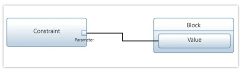
Adding a Connector Parameters and Values
The example used below connects two ‘Block’ constructs with a ‘Connector’ construct.
- Within a ‘Parametric Diagram,’ select the ‘Parameter’ you would like connected to a ‘Value.’

- Click the green circle and continue to hold down the left mouse button.

- Drag the green circle over to another ‘Value’ of your choice.

- When the other ‘Block’ box highlights green, release the left mouse button to drop the new ‘Connector’ and add it to the diagram.

Notice the ‘Connector’ stays selected once it has been dropped. Since it is selected, the toolbar changes to include buttons for functions that can be used on the construct. The sidebar also changes to include additional ‘Metadata,’ ‘Attributes,’ and ‘Relationships’ tabs. - Once added to the diagram, enter a meaningful ‘Name’ for your new ‘Connector’ via the ‘Attributes’ tab of the left sidebar (focused automatically for convenience).

- Click the ‘Save’ button located on the toolbar to persist your changes to your project’s database.

* Note: The above process describes using the ‘New’ tab of the left sidebar, which automatically generates a new entity to represent each new diagram construct. If you would like to reuse existing entities from your database to represent a new construct, use the ‘Existing’ tab instead.
Removing a Construct
A construct can be easily removed from a ‘Parametric Diagram‘.
- Within a ‘Parametric Diagram,’ select the construct you wish to remove. This will make the toolbar appear with applicable functions which can be used on the selected construct.

- Click the ‘Remove’ button to remove the construct from the diagram (as the default action).

* Note: The ‘Remove’ button also includes a drop-down menu where you can select ‘Delete from Database’ or the default option of ‘Remove from Diagram.’
Tutorial Video
To continue learning about SysML Diagrams, Click Here.
(Next Article: Parametric Diagram Modifications & Settings)