
Using Layer Diagrams
| Function | Description |
|---|---|
| Creating Layer Diagrams | Using ‘Diagrams View’ in Innoslate, you can create a new ‘Layer Diagram.’ |
| Layer Diagram Constructs | The ‘Layer Diagram’ supports two unique diagram constructs: an ‘Asset’ and a ‘Conduit.’ |
| Adding an Asset | An ‘Asset’ construct can be added to a ‘Layer Diagram’ via drag-and-drop. |
| Adding a Conduit | A ‘Conduit’ construct can be added to a ‘Layer Diagram’ via drag-and-drop. |
| Assigning Decomposition | You can assign decomposition within a ‘Layer Diagram.’ |
| Removing a Construct | A construct can be easily removed from a ‘Layer Diagram.’ |
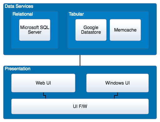
Layer Diagrams help you categorize the physical elements in your system into meaningful and abstract layers. These layers describe major tasks that the elements perform or the major components of your system. Each layer can also include sub-layers that provide a more detailed description of the components within them. With Layer Diagrams, you can visualize multiple levels of physical decomposition and linking Conduits.
Creating Layer Diagrams
Within the ‘Diagrams Dashboard,’ users can create a new diagram by clicking the ‘ New Diagram’ button in the top right corner of the page.

Clicking the ‘ New Diagram’ button will open the New Diagram dialog where you will be directed through the process of creating a new diagram.
Create a Layer Diagram
- Choose Which Type of Diagram to Create
In step 1, select ‘Layer Diagram,’ under ‘General,’ as your diagram type.

Click the ‘Next’ button.

2. Specify New Root Action Information
In step 2, you will be prompted to input a diagram ‘Name,’ ‘Number’ (optional), and ‘Description’ (optional). Then, click the ‘Finish’ button.

Layer Diagram Constructs
The ‘Layer Diagram’ supports two unique diagram constructs: an ‘Asset’ and a ‘Conduit.’ Each diagram construct is described in more detail below:
-
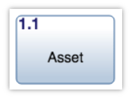
Asset
This construct is used to capture the physical components of a system.
In the system model, a simple Asset entity is generated to represent an ‘Asset’ construct with no additional diagram-specific information. Innoslate’s default database schema includes labels to specify the type of this Asset entity as a(n) Architecture, Block, Context, Environment, External System, Facility, Infrastructure, Materiale, Organization, Package, Personnel, Segment, Service, Subsystem, and/or System.
In the diagram, this construct is represented as a rounded block containing the number and name of the ‘Asset.’
-
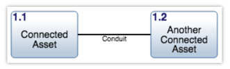
Conduit
This construct is used to capture the relationships between the physical components of a system.
In the system model, a Conduit entity is generated to represent a ‘Conduit’ construct with a “connects to” relationship to each of the entities which represent the two connected constructs. Innoslate’s default database schema includes labels to specify the type of this Conduit entity as a(n) Aggregation, Association, Cable, Composition, Downlink, Interface, Network, Pipe, Roadway, Uplink, and/or Wireless.
In the diagram, this construct is represented as a solid line connecting two ‘Asset’ constructs and a line label containing the name of the ‘Conduit.’
Adding an Asset
An ‘Asset’ construct can be added to a ‘Layer Diagram‘ via drag-and-drop.
- Within a ‘Layer Diagram,’ click the ‘Asset’ icon in the ‘New’ tab of the left sidebar and continue to hold down the left mouse button.

- Drag the ‘Asset’ icon over to the adjacent diagram canvas.

- Release the left mouse button while over the diagram canvas to drop the new ‘Asset’ and add it to the diagram.

Notice the ‘Asset’ stays selected once it has been dropped. Since it is selected, the toolbar changes to include buttons for functions which can be used on the construct. The sidebar also changes to include additional ‘Metadata,’ ‘Attributes’ and ‘Relationships’ tabs.
- Once added to the diagram, enter a meaningful ‘Name’ for your new ‘Asset’ via the ‘Attributes’ tab of the left sidebar (focused automatically for convenience).

- Click the ‘Save’ button located on the toolbar to persist your changes to your project’s database.

* Note: The above process describes using the ‘New’ tab of the left sidebar, which automatically generates a new entity to represent each new diagram construct. If you would like to reuse existing entities from your database to represent a new construct, use the ‘Existing’ tab instead.
For more information on this construct and how it is represented in the database model, see Layer Diagram Constructs.
Adding a Conduit
A ‘Conduit’ construct can be added to a ‘Layer Diagram‘ via drag-and-drop between two 'Asset' constructs on the canvas.
- Within a ‘Layer Diagram,’ select the ‘Asset’ you would like connected to another ‘Asset.’

- Click one of the green circles on the selected ‘Asset’ and continue to hold down the left mouse button.

- Drag the green circle over to another ‘Asset’ of your choice.

- When the other ‘Asset’ box highlights green, release the left mouse button to drop the new ‘Conduit’ and add it to the diagram.

Notice the ‘Conduit’ stays selected once it has been dropped. Since it is selected, the toolbar changes to include buttons for functions that can be used on the construct. The sidebar also changes to include additional ‘Metadata,’ ‘Attributes’ and ‘Relationships’ tabs.
- Once added to the diagram, enter a meaningful ‘Name’ for your new ‘Conduit’ via the ‘Attributes’ tab of the left sidebar (focused automatically for convenience).

- Click the ‘Save’ button located on the toolbar to persist your changes to your project’s database.

* Note: For more information on this construct and how it is represented in the database model, see Layer Diagram Constructs.
Assigning Decomposition
‘Decomposition’ can be assigned within a ‘Layer Diagram’ via drag-and-drop. The parent asset construct must be added to the diagram first before decomposition can be assigned.
- Within a ‘Layer Diagram,’ already containing the parent ‘Asset,’ click to add a new ‘Asset’ in the ‘New’ tab of the left sidebar and continue to hold down the left mouse button.

- Drag the ‘Asset’ icon over to the adjacent diagram canvas.

- Drag the ‘Asset’ over the parent ‘Asset.’ When the parent ‘Asset’ box highlights green, release the left mouse button to drop the new ‘Asset’ and add it to the diagram.

Notice the new ‘Asset’ stays selected once it has been dropped. Since it is selected, the toolbar changes to include buttons for functions that can be used on the construct. The sidebar also changes to include additional ‘Metadata,’ ‘Attributes’ and ‘Relationships’ tabs.
- You will notice that the parent ‘Asset’ automatically enlarges and becomes a shade of blue, with the new child ‘Asset’ now existing within the parent representing a decomposed by/decomposes relationship.

- Once added to the diagram, enter a meaningful ‘Name’ for your new ‘Asset’ via the ‘Attributes’ tab of the left sidebar (focused automatically for convenience).

- Click the ‘Save’ button located on the toolbar to persist your changes to your project’s database.

Removing a Construct
A construct can be easily removed from a ‘Layer Diagram.’
- Within a ‘Layer Diagram,’ select the construct you wish to remove. This will make the toolbar appear with applicable functions which can be used on the selected construct.

- Click the ‘Remove’ button to remove the construct from the diagram (as the default action).

* Note: The ‘Remove’ button also includes a drop-down menu where you can select ‘Delete from Database’ or the default option of ‘Remove from Diagram.’
To continue learning about General Diagrams, Click Here.
(Next Article: Layer Diagram Modifications & Settings)