
Using Block Definition Diagrams
| Function | Description |
|---|---|
| Creating Block Definition Diagrams | Using ‘Diagrams View’ in Innoslate, you can create a new ‘Block Definition Diagram’. |
| Block Definition Diagram Constructs | The ‘Block Definition Diagram’ supports eight unique diagram constructs: a ‘Block,’ a ‘Port,’ a ‘Value,’ a ‘Constraint,’ an ‘Operation,’ an ‘Input Parameter,’ a ‘Return Type,’ and a ‘Logical Connection.’ |
| Adding a Block | A ‘Block’ construct can be added to a ‘Block Definition Diagram’ via drag-and-drop. |
| Adding a Port | A ‘Port’ construct can be added to a ‘Block Definition Diagram’ via drag-and-drop. |
| Adding a Value | A ‘Value’ construct can be added to a ‘Block Definition Diagram’ via drag-and-drop. |
| Adding a Constraint | A ‘Constraint’ construct can be added to a ‘Block Definition Diagram’ via drag-and-drop. |
| Adding an Operation | An ‘Operation’ construct can be added to a ‘Block Definition Diagram’ via drag-and-drop. |
| Adding an Input Parameter | An ‘Input Parameter’ construct can be added to a ‘Block Definition Diagram’ via drag-and-drop. |
| Adding a Return Type | A ‘Return Type’ construct can be added to a ‘Block Definition Diagram’ via drag-and-drop. |
| Adding a Logical Connection | A ‘Logical Connection’ construct can be added to a ‘Block Definition Diagram’ via drag-and-drop. |
| Assigning Decomposition | The child of a ‘Block’ construct can be assigned in the ‘Block Definition Diagram’ via drag-and-drop. |
| Removing a Construct | A construct can be easily removed from a ‘Block Definition Diagram.’ |
The ‘Block Definition Diagram’ is a structure diagram showing blocks, their attributes, and their hierarchical relationships.

Creating Block Definition Diagrams
Within the ‘Diagrams Dashboard,’ users can create a new diagram by clicking the ‘ New Diagram’ button in the top right corner of the page.
Clicking the ‘ Create Diagram’ button will open the New Diagram dialog where you will be directed through the process of creating a new diagram.
Create a Block Definition Diagram
- Choose Which Type of Diagram to Create
In step 1, select ‘Block Definition Diagram,’ under ‘SysML,’ as your diagram type.

Click the ‘Next’ button.

- Specify New Root Action Information
In step 2, you will be prompted to input a diagram ‘Name,’ ‘Number’ (optional), and ‘Description’ (optional). Then, click the ‘Finish’ button to save and automatically open your new Block Definition Diagram.

Block Definition Diagram Constructs
The ‘Block Definition Diagram’ supports eight unique diagram constructs: a ‘Block,’ a ‘Port,’ a ‘Value,’ a ‘Constraint,’ an ‘Operation,’ an ‘Input Parameter,’ a ‘Return Type,’ and a ‘Logical Connection.’ Each diagram construct is described in more detail below:
-
Block
In the system model, an Asset entity with the label ‘Block’ is used to represent a ‘Block’ construct. A ‘Block’ must be added to the diagram first before any of the other constructs can be added. In the diagram, this construct is represented as a rounded box and contains the name of the ‘Block’ in the top section.
-
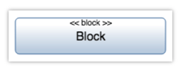
Port
In the system model, a Port entity is used to represent a ‘Port’ construct. A ‘Block’ must be added to the diagram first before this construct can be added. In the diagram, this construct is represented as a small square on the edge of a ‘Block’ with the name of the ‘Port’ underneath. A Port will create the decomposes relationship to the Block entity.
-
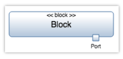
Value
In the system model, a Characteristic entity is used to represent a ‘Value’ construct. A ‘Block’ must be added to the diagram first before this construct can be added. In the diagram, this construct is represented as a line of text containing the name of the ‘Value,’ a semicolon, and the units of the ‘Value’ in the middle section of the ‘Block.’ Adding a Value will create a specifies relationship to the Block entity.
-
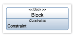
Constraint
In the system model, an Equation entity is used to represent a ‘Constraint’ construct. A ‘Block’ must be added to the diagram first before this construct can be added. In the diagram, this construct is represented as a line of text containing the name of the ‘Constraint’ in the bottom section of the ‘Block.’ Adding a Constraint will create an equation for relationship to the Block.
-
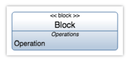
Operation
In the system model, an Action entity is used to represent an ‘Operation’ construct. A ‘Block’ must be added to the diagram first before this construct can be added. In the diagram, this construct is represented as a line of text containing the name of the ‘Operation’ in the bottom section of the ‘Block.’ Adding an Operation construct to a block will create the performed by relationship.
-
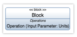
Input Parameter
In the system model, an Input/Output entity is used to represent an ‘Input Parameter’ construct. An ‘Operation’ must first be added to a ‘Block’ in the diagram before this construct can be added. In the diagram, this construct is represented as a line of text containing the name and units of the ‘Input Parameter’ in parenthesis. Adding an Input Parameter will create a received by relationship to the Operation.
-
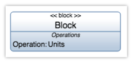
Return Type
In the system model, an Input/Output entity is used to represent a ‘Return Type’ construct. An ‘Operation’ must first be added to a ‘Block’ in the diagram before this construct can be added. In the diagram, this construct is represented as a semicolon and a line of text containing the units of the ‘Return Type.’ Adding a Return Type to an Action will create a generated by relationship to the Operation.
-
Logical Connection
In the system model, a Logical entity is used to represent a ‘Logical Connection’ construct. At least two ‘Block’ constructs must be added to the diagram first before a ‘Logical Connection’ can be added. In the diagram, this construct is represented as a solid line connecting two ‘Block’ constructs and a line label containing the name of the ‘Logical Connection.’

Logical Connection Types
The differences in the Logical Connections construct depends on the path chosen between Blocks. Each Path's appearance is explained below.
Composition Path
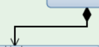
When 2 blocks are connected with the Composition Path, there will be a black diamond on the Parent block and arrow on the child block.
Aggregation Path

When 2 blocks are using the Aggregation Path, there will be a white diamond on the initial block and arrow on the block it is pointed to.
Simple Association Path
There will be a black line with no diamonds or arrows indicating the 2 blocks connected are using the Simple Association Path.
Adding a Block
A ‘Block’ construct can be added to a ‘Block Definition Diagram‘ via drag-and-drop. A ‘Block’ must be added to the diagram first before any of the other constructs can be added.
- Within a ‘Block Definition Diagram,’ click the ‘Block (Asset)’ icon in the ‘New’ tab of the left sidebar and continue to hold down the left mouse button.

- Drag the ‘Block (Asset)’ icon over to the adjacent diagram canvas.

- Release the left mouse button while over the diagram canvas to drop the new ‘Block’ and add it to the diagram.

Notice the ‘Block’ stays selected once it has been dropped. Since it is selected, the toolbar changes to include buttons for functions that can be used on the construct. The sidebar also changes to include additional ‘Metadata,’ ‘Attributes,’ and ‘Relationships’ tabs.
- Once added to the diagram, enter a meaningful ‘Name’ for your new ‘Block’ via the ‘Attributes’ tab of the left sidebar (focused automatically for convenience).

- Click the ‘Save’ button located on the toolbar to persist your changes to your project’s database.

* Note: The above process describes using the ‘New’ tab of the left sidebar, which automatically generates a new entity to represent each new diagram construct. If you would like to reuse existing entities from your database to represent a new construct, use the ‘Existing’ tab instead.
Adding a Port
A ‘Port’ construct can be added to a ‘Block Definition Diagram‘ via drag-and-drop. A ‘Block’ must be added to the diagram first before this construct can be added.
-
Within a ‘Block Definition Diagram,’ click the ‘Port (Port)’ icon in the ‘New’ tab of the left sidebar and continue to hold down the left mouse button.

-
Drag the ‘Port (Port)’ icon over to the bottom section of the destination ‘Block’ of your choice.

-
When the ‘Block’ box highlights green, release the left mouse button to drop the new ‘Port’ and add it to the diagram.

Notice the ‘Port’ stays selected once it has been dropped. Since it is selected, the toolbar changes to include buttons for functions that can be used on the construct. The sidebar also changes to include additional ‘Metadata,’ ‘Attributes,’ and ‘Relationships’ tabs.
-
Once added to the diagram, enter a meaningful ‘Name’ for your new ‘Port’ via the ‘Attributes’ tab of the left sidebar (focused automatically for convenience).

-
Click the ‘Save’ button located on the toolbar to persist your changes to your project’s database.

* Note: The above process describes using the ‘New’ tab of the left sidebar, which automatically generates a new entity to represent each new diagram construct. If you would like to reuse existing entities from your database to represent a new construct, use the ‘Existing’ tab instead.
Adding a Value
A ‘Value’ construct can be added to a ‘Block Definition Diagram‘ via drag-and-drop. A ‘Block’ must be added to the diagram first before this construct can be added.
-
Within a ‘Block Definition Diagram,’ click the ‘Value (Characteristic)’ icon in the ‘New’ tab of the left sidebar and continue to hold down the left mouse button.

-
Drag the ‘Value (Characteristic)’ icon over to the middle section of the destination ‘Block’ of your choice.

-
When the ‘Block’ box highlights green, release the left mouse button to drop the new ‘Value’ and add it to the diagram.

Notice the ‘Value’ stays selected once it has been dropped. Since it is selected, the toolbar changes to include buttons for functions that can be used on the construct. The sidebar also changes to include additional ‘Metadata,’ ‘Attributes,’ and ‘Relationships’ tabs.
-
Once added to the diagram, enter a meaningful ‘Name’ for your new ‘Value’ via the ‘Attributes’ tab of the left sidebar (focused automatically for convenience).

-
Click the ‘Save’ button located on the toolbar to persist your changes to your project’s database.

* Note: The above process describes using the ‘New’ tab of the left sidebar, which automatically generates a new entity to represent each new diagram construct. If you would like to reuse existing entities from your database to represent a new construct, use the ‘Existing’ tab instead.
Adding a Constraint
A ‘Constraint’ construct can be added to a ‘Block Definition Diagram‘ via drag-and-drop. A ‘Block’ must be added to the diagram first before this construct can be added.
-
Within a ‘Block Definition Diagram,’ click the ‘Constraint (Equation)’ icon in the ‘New’ tab of the left sidebar and continue to hold down the left mouse button.

-
Drag the ‘Constraint (Equation)’ icon over to the bottom section of the destination ‘Block’ of your choice.

-
When the ‘Block’ box highlights green, release the left mouse button to drop the new ‘Constraint’ and add it to the diagram.

Notice the ‘Constraint’ stays selected once it has been dropped. Since it is selected, the toolbar changes to include buttons for functions that can be used on the construct. The sidebar also changes to include additional ‘Metadata,’ ‘Attributes,’ and ‘Relationships’ tabs.
-
Once added to the diagram, enter a meaningful ‘Name’ for your new ‘Constraint’ via the ‘Attributes’ tab of the left sidebar (focused automatically for convenience).

-
Click the ‘Save’ button located on the toolbar to persist your changes to your project’s database.

* Note: The above process describes using the ‘New’ tab of the left sidebar, which automatically generates a new entity to represent each new diagram construct. If you would like to reuse existing entities from your database to represent a new construct, use the ‘Existing’ tab instead.
Adding an Operation
An ‘Operation’ construct can be added to a ‘Block Definition Diagram‘ via drag-and-drop. A ‘Block’ must be added to the diagram first before this construct can be added.
- Within a ‘Block Definition Diagram,’ click the ‘Operation (Action)’ icon in the ‘New’ tab of the left sidebar and continue to hold down the left mouse button.

- Drag the ‘Operation (Action)’ icon over to the bottom section of the destination ‘Block’ of your choice.

- When the ‘Block’ box highlights green, release the left mouse button to drop the new ‘Operation’ and add it to the diagram.

Notice the ‘Operation’ stays selected once it has been dropped. Since it is selected, the toolbar changes to include buttons for functions that can be used on the construct. The sidebar also changes to include additional ‘Metadata,’ ‘Attributes,’ and ‘Relationships’ tabs.
- Once added to the diagram, enter a meaningful ‘Name’ for your new ‘Operation’ via the ‘Attributes’ tab of the left sidebar (focused automatically for convenience).

- Click the ‘Save’ button located on the toolbar to persist your changes to your project’s database.

* Note: The above process describes using the ‘New’ tab of the left sidebar, which automatically generates a new entity to represent each new diagram construct. If you would like to reuse existing entities from your database to represent a new construct, use the ‘Existing’ tab instead.
Adding an Input Parameter
An ‘Input Parameter’ construct can be added to a ‘Block Definition Diagram‘ via drag-and-drop. An ‘Operation’ must first be added to a ‘Block’ in the diagram before this construct can be added.
-
Within a ‘Block Definition Diagram,’ click the ‘Input Parameter (Input/Output)’ icon in the ‘New’ tab of the left sidebar and continue to hold down the left mouse button.

-
Drag the ‘Input Parameter (Input/Output)’ icon over to the bottom section of the ‘Block’ of the destination ‘Operation’ of your choice.

-
When the ‘Operation’ box highlights green, release the left mouse button to drop the new ‘Input Parameter’ and add it to the diagram.

Notice the ‘Input Parameter’ stays selected once it has been dropped. Since it is selected, the toolbar changes to include buttons for functions that can be used on the construct. The sidebar also changes to include additional ‘Metadata,’ ‘Attributes,’ and ‘Relationships’ tabs.
-
Once added to the diagram, enter a meaningful ‘Name’ for your new ‘Input Parameter’ via the ‘Attributes’ tab of the left sidebar (focused automatically for convenience).

-
Click the ‘Save’ button located on the toolbar to persist your changes to your project’s database.

* Note: The above process describes using the ‘New’ tab of the left sidebar, which automatically generates a new entity to represent each new diagram construct. If you would like to reuse existing entities from your database to represent a new construct, use the ‘Existing’ tab instead.
Adding a Return Type
A ‘Return Type’ construct can be added to a ‘Block Definition Diagram‘ via drag-and-drop. An ‘Operation’ must first be added to a ‘Block’ in the diagram before this construct can be added.
-
Within a ‘Block Definition Diagram,’ click the ‘Return Type (Input/Output)’ icon in the ‘New’ tab of the left sidebar and continue to hold down the left mouse button.

-
Drag the ‘Return Type (Input/Output)’ icon over to the bottom section of the ‘Block’ of the destination ‘Operation’ of your choice.

-
When the ‘Operation’ box highlights green, release the left mouse button to drop the new ‘Return Type’ and add it to the diagram.

Notice the ‘Return Type’ stays selected once it has been dropped. Since it is selected, the toolbar changes to include buttons for functions that can be used on the construct. The sidebar also changes to include additional ‘Metadata,’ ‘Attributes,’ and ‘Relationships’ tabs.
-
Once added to the diagram, you can specify the unit(s) for your ‘Return Type’ under the ‘Attributes’ tab of the left sidebar.

-
Click the ‘Save’ button located on the toolbar to persist your changes to your project’s database.

* Note: The above process describes using the ‘New’ tab of the left sidebar, which automatically generates a new entity to represent each new diagram construct. If you would like to reuse existing entities from your database to represent a new construct, use the ‘Existing’ tab instead.
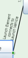
Adding a Logical Connection
A ‘Logical Connection’ can be added to the ‘Block Definition Diagram‘ via drag-and-drop. The example used on this page connects two ‘Block’ constructs with a ‘Logical Connection.’
-
Within a ‘Block Definition Diagram,’ select the ‘Block’ you would like connected to another ‘Block’.

-
Click the green circle and continue to hold down the left mouse button.

-
Drag the green circle over to another ‘Block’ of your choice.

-
When the parent ‘Block’ box highlights green, release the left mouse button over the ‘Simple Association (connected by)’ section to drop the new ‘Logical Connection’ and add it to the diagram.

Notice the ‘Logical Connection’ stays selected once it has been dropped. Since it is selected, the toolbar changes to include buttons for functions that can be used on the construct. The sidebar also changes to include additional ‘Metadata,’ ‘Attributes,’ and ‘Relationships’ tabs.
-
Once added to the diagram, enter a meaningful ‘Name’ for your new ‘Logical Connection’ via the ‘Attributes’ tab of the left sidebar (focused automatically for convenience).

- Click the ‘Save’ button located on the toolbar to persist your changes to your project’s database.

* Note: The above process describes using the ‘New’ tab of the left sidebar, which automatically generates a new entity to represent each new diagram construct. If you would like to reuse existing entities from your database to represent a new construct, use the ‘Existing’ tab instead.
Assigning Decomposition
The child of a ‘Block’ construct can be assigned in the ‘Block Definition Diagram‘ via drag-and-drop. Both the “to-be” parent and child ‘Block’ constructs must be added to the diagram first before the parent can be assigned.
-
Within a ‘Block Definition Diagram,’ select the child ‘Block’ to which you would like to assign the parent.

-
Click the green circle and continue to hold down the left mouse button.

-
Drag the green circle over to the parent ‘Block’ of your choice.

-
When the parent ‘Block’ box highlights green, release the left mouse button over the ‘Composition (decomposed by)’ section to add a decomposes/decomposed by relationship.

-
Once added to the diagram, the new relationship should appear as an arrow between the two ‘Block’ constructs. Click the ‘Save’ button located on the toolbar to persist your changes to your project’s database.

Removing a Construct
A construct can be easily removed from a 'Block Definition Diagram'
- Within a ‘Block Definition Diagram,’ select the construct you wish to remove. This will make the toolbar appear with applicable functions which can be used on the selected construct.

- Click the ‘Remove’ button to remove the construct from the diagram (as the default action).

* Note: The ‘Remove’ button also includes a drop-down menu where you can select ‘Delete from Database’ or the default option of ‘Remove from Diagram.’
Tutorial Video
To continue learning about SysML Diagrams, Click Here.
(Next Article: Block Definition Diagram Modifications & Settings)